Continue to Site

Welcome to EDAboard.com

Welcome to our site! EDAboard.com is an international Electronics Discussion Forum focused on EDA software, circuits, schematics, books, theory, papers, asic, pld, 8051, DSP, Network, RF, Analog Design, PCB, Service Manuals... and a whole lot more! To participate you need to register. Registration is free. Click here to register now.

Antenna preamplifier

Status
Not open for further replies.

I14R10

Full Member level 3
Joined
May 31, 2015
Messages
185
Helped
0
Reputation
0
Reaction score
0
Trophy points
1,296
Activity points
2,750
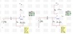
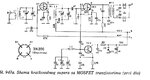
Can you help me and take a look at this amplifiers? They are supposed to be antenna preamplifiers. On the left side is my calculated FET amplifier. On the right side the drain resistor is replaced with LC circuit that resonates on 14MHz. Yes I know, the input is 14.25MHz. I calculated it by mistake for 14MHz, but it's not important. The input signal is in reality coming from the antenna connected like L1/L2 in this schematics attached below. I also have a capacitor parallel with L2.

What I want to ask is: I want to use the circuit on the right side of my schematics because it has higher gain, but I don't know if it will work. Did I design it correctly? Do you have some improvements that I could put inside my schematics? I'm building a 14MHz receiver and this is really the most important part of the entire radio.
 

Attachments

  • amplifiers.jpg
    amplifiers.jpg
    491.4 KB · Views: 127
  • antena.jpg
    antena.jpg
    136.6 KB · Views: 116
Last edited by a moderator:

From the posted schematics my understanding is that you want to replace the dual-gate amplifier (TR1) with a JFET amplifier (Q2).
It will work, perhaps with minor changes. Replace C3 and C4 capacitors (15uF) with 47nF capacitors, and also might need to change the JFET resonant circuit L2/C5 ratio to L2=1uH and C5=130pF.
In my opinion I think is better to keep the dual-gate as an amplifier (the gain is almost the same as JFET) because this can provide AGC on gate nr. 2.
 

Not really, I am using the schematics on the left, and instead that signal sources I use antenna with LC circuit like on the schematics on the right. Just L1, L2 and C1. And that is the only part I am using from right schematics. Sorry about misunderstanding, It's quite difficult to describe something in english for me.

I wanted to ask If I designed that amplifiers on the left correctly. Both of them. Right one has higher gain but I have only that simulation to confirm it.
 

The sensitivity of a receiver with sufficient gain (can be expected for modern receiver designs) is limited by the noise factor and impedance matching of the input stage. Adding more gain can't improve it, only (if feasible at all) using a preampifier with lower noise.

It's not obvious at first sight if a JFET amplifier can improve the receiver sensitivity, and if under which prerequisitions. One important point is antenna impedance. Operating a preamplifier without an input LC circuit brings up the risk of overloading it with off-band signals.
 

It's not for the modern receiver. I'm building 14MHz receiver from scratch. I know I can just buy a kit but that's not really interesting and fun.
 

Are there any tips on how to choose source resistor when you have LC circuit in drain? LC circuit has its impedance. Do we just calculate it and treat it like regular resistor?
 

The FET source resistor is necessary for the DC bias setting, and the LC drain circuit has little influence in this matter.

**broken link removed**
 
  • Like
Reactions: I14R10

    I14R10

    Points: 2
    Helpful Answer Positive Rating
The FET source resistor is necessary for the DC bias setting, and the LC drain circuit has little influence in this matter.

**broken link removed**

At 14 MHz it makes not too much sense to install a preamplifier next to an antenna. Noise level is quite high from ionosphere and using a preamp may make any improvement only if you use a long and lossy cable to receiver.
Many good simple receivers for 14 MHz band use input mixers only and no preamp is needed.
To make a simple receiver you can use a preamp but almost to no advantage. Such preamp may rather contribute by adding intermoduation by stronger unwanted signals .
 
  • Like
Reactions: I14R10

    I14R10

    Points: 2
    Helpful Answer Positive Rating
I understand how the biasing is done. I calculated the impedance of that LC circuit at frequency 14.25MHz. It's around 81M ohm. How does that work? If I put 81M ohm resistor there (in drain), the circuit probably would not work, but with LC circuit it does.

At 14 MHz it makes not too much sense to install a preamplifier next to an antenna. Noise level is quite high from ionosphere and using a preamp may make any improvement only if you use a long and lossy cable to receiver.
Many good simple receivers for 14 MHz band use input mixers only and no preamp is needed.
To make a simple receiver you can use a preamp but almost to no advantage. Such preamp may rather contribute by adding intermoduation by stronger unwanted signals .

I will need to have at least 15m of coaxial cable from radio to the antenna. It will go through my window, on the roof. I thought that I should put preamplifier.

BTW, I thought about adding one more stage of JFET after this one (in preamp), but as you said that there is almost no need to use preamplifier at all, then probably I have nothing to gain by adding one more amplification stage.
 
Last edited:

This is true, if in the front of the receiver it's a gain antenna for sure is no necessary an amplifier before the mixer, even if the schematic use a passive mixer (with no gain).
But in most cases people use wire antennas with no gain, but some loss from the feeder, so a simple amplifier will improve the signal-to-noise ratio of the receiver.
Ideally is to use a switchable amplifier (using switching diodes, or signal relays) and depending by different conditions you can turn ON/OFF the preamplifier.
 
  • Like
Reactions: I14R10

    I14R10

    Points: 2
    Helpful Answer Positive Rating
That is a great idea. I will do it that way.
 

What would you recommend to use as antenna preamplifier, common source tuned FET amplifier or tuned cascode amplifier?
 

For an HF receiver, I would go for a common gate differential FET amplifier, which is a good compromise between linearity, gain, and noise figure.
 

Here is the circuit I made as antenna preamplifier. But there is one thing that I don't understand - L2 and L3 inductors, they are for impedance matching. Input impedance of this amplifier is 1M ohm and I have to match it to 50 ohms that the antenna wants.
In resonance, at 14MHz the impedance of LC tank circuit L2 and C4 is infinite, but they are connected parallel to 1M ohm on FET gate so the impedance is 1M ohm. So, I would need turn ratio of 141 to get match the impedances.

Is this correct? Could I put 100k resistor on FET gate so the turn ratio would be smaller?

And vfone, I did not forget about your advice, I'm looking into it and making calculations. It's just that I have this one calculated and this thing with impedances was bugging me.

- - - Updated - - -

Sorry, I did not attach anything. Here it is

amp.png
 

Since nobody answered I'm going to continue to discuss this with myself. How do you do the switching from transmitting and receiving? If I use only the mixer in both TX and RX it's easy, but if I use filters in both TX and RX the things get complicated.
 
Last edited:

As I mentioned, at under 50 MHz the ionospheric noise is high and a preamp makes no sense. With one antenna used lso to transmit you must use a good RF switch, and the preamp must be protected by DC bias to save it.

Look into ARRL Radio Amateurs" Handbook, to see how professional transceivers work.
 
  • Like
Reactions: I14R10

    I14R10

    Points: 2
    Helpful Answer Positive Rating
Thanks, but this is not about preamplifier. It was about how transceivers switch from receiving to transmitting, and what components are used in both of them. If I sound confused that's because I'm reading a lot from many different sources, including ARRL handbook. But there are some things that are not really explained so I have to ask them here.
 

Thanks, but this is not about preamplifier. It was about how transceivers switch from receiving to transmitting, and what components are used in both of them. If I sound confused that's because I'm reading a lot from many different sources, including ARRL handbook. But there are some things that are not really explained so I have to ask them here.

OK, then to switch one needs a coaxial T-R switch, there also smaller RF switches with a good isolation. Next for under 30 MHz, PIN diodes are not good, so a wideband FET preamplifier (really low gain) is DC-biased during TX operation to block the strong signal. In addition, AGC blocks the IF amplifier as needed.
All this switching is relatively slow, like 100 ms. Transceiver makers may use different circuits. Some are activated by microphone TX switch, others by keying signal to the transmitter PA.
 

What about switching it with simple relay? For example, one relay before IF amp, one after, also one before SSB filter and one aster. For receiving relay is in one position, for transmitting the relay is in other position that reverses the order.

For example

Relay 1 position
IF amp-> SSB filter


Relay 2 position
|--------------------------<
>---> IF amp SSB filter ----^
 

Seriously, on the HF bands you do not need a preamp, and adding one will make things worse....

Start with a 14MHz BPF to remove as much of the out of band energy as you can, then a mixer (with diplexers on all ports to provide correct wideband termination is a nice touch, but you can add those once it works), then place your IF filter, then the IF amp...

Doing it that way you expose each stage to as little energy as possible, minimizing intermod products, you dont want the IF amp exposed to the whole 14MHz band if you can avoid it, which is why it goes after the main selectivity.

For TR switching, some combination of relays and diode switching is normal, have a look at the Picastar for an interesting bidirectional amplifier.

Do you have a copy of EMRFD?

Regards, Dan.
 

Status
Not open for further replies.

Part and Inventory Search

Welcome to EDABoard.com

Sponsor

Back
Top