Continue to Site

Welcome to EDAboard.com

Welcome to our site! EDAboard.com is an international Electronics Discussion Forum focused on EDA software, circuits, schematics, books, theory, papers, asic, pld, 8051, DSP, Network, RF, Analog Design, PCB, Service Manuals... and a whole lot more! To participate you need to register. Registration is free. Click here to register now.

Antenna: How to improve radiation efficiency! Why?

Status
Not open for further replies.

Sherry1

Member level 3
Member level 3
Joined
Apr 4, 2013
Messages
61
Helped
0
Reputation
0
Reaction score
0
Trophy points
1,286
Location
Manchester, UK
Visit site
Activity points
1,810
I came up with a preliminary antenna design which has a fair return loss, S11 = -14dB in simulation at 1.5GHz
However it has poor radiation efficiency as shown in figure
Antenna pattern.png

Radiation efficiency = -29.64dB
Total efficiency = -29.79dB
How can I improve it? What is the standard range of radiation efficiency for a good RX antenna?

Quick note:
1. This is intended to be used for receiver system.
2. Ground plane = 40x20mm.
3. Its a slot antenna.
 

Re: Antenna: Good S11 but poor radiation efficiency! Why?

According to IEEE specification, radiation efficiency is radiated/accepted power. Means S11 doesn't even count for it. Your measurement says that 99.9 % of the input power is dissipated inside the antenna. It's hard to imagine how you designed the antenna to achieve this perfect annihilation of RF power. More likely you didn't manage to setup the simulation correctly.
 

Re: Antenna: Good S11 but poor radiation efficiency! Why?

I can do one. just put a 50 ohm chip resistor at the end of a coax. Good S11 but almost no radiation
 

Re: Antenna: Good S11 but poor radiation efficiency! Why?

I can't see what structure you simulated. What is behind your slot (air, dielectric, metal, combination, etc)?
What is the useful bandwidth (for example where VSWR=2, or RL = 9.5 dB)? If relatively wide, there must be huge dissipation (as suggested by the radiation efficiency). If very narrow, then sure something is wrong with the simulation setup.

Check the properties of dielectric layers (if any), maybe you made some entry error in tan(delta)
Check the properties of conducting layers (just to find some entry error).
 

Re: Antenna: Good S11 but poor radiation efficiency! Why?

The radiated field of the slot antenna could be very much affected by the location of the connection point, mainly due to the inducted field and current distribution within the slot perimeter, which contributes to radiation.
This is in opposite compared to basic patch antennas, where the connection point affect generally the return loss of the antenna.
 

Re: Antenna: Good S11 but poor radiation efficiency! Why?

I can well imagine that the OP managed to design a bad or even a very bad antenna. But I have serious difficulties to understand how 99.9 % of the input power can be absorbed without an intentionally built-in absorbing element (as ironically suggested by chuckey in post #3).
 

Re: Antenna: Good S11 but poor radiation efficiency! Why?

I am shocked at my talent of screwing up :-?

WimRFP: RL=-14dB at 1.5GHz and its not intended to be wideband. Copper has dielectric behind it which is supposed to have er=3.2 at 1.5GHz. So while defining new material of substrate, I put tan(delta) = 0.002 and er=3.4 at 1MHz ( or 0.001GHz)

FvM and vfone: I used CPW Feed and Waveguide port (3*w and in height and 4* Height of ground plane) just at the edge of Grounded CPW and position is centered around it.

Boundary conditions are 'open ( add space )' in all directions...
I can post my project if you can kindly check it?
 

Re: Antenna: Good S11 but poor radiation efficiency! Why?

Why are you defining your parameters at 0.001 GHz, though your design uses 1.5 GHz?

You may post a graph that shows your structure, as I don't have a good idea of your structure. I don't have HFSS or CST so I can't check your files.

It is likely that some simulator setting isn't fine as settings for dielectric are fine (assuming that the value for 1 MHz is also used for 1.5 GHz). Can you start with a simple half wave antenna (or other antenna that you know well)? Just to make sure the simulator is running well.

In my opinion, your receive antenna should have > 50% radiation efficiency, otherwise thermal noise may reduce system performance. If your simulator supports infinite dielectrics only, the radiation efficiency in simulation may be less then in real world. You can check this by using a vertically polarized antenna above the dielectric layer.
 

Re: Antenna: Good S11 but poor radiation efficiency! Why?

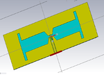
slot.png

It is grounded CPW feed and the red rectangle is a waveguide port, it coincides with edge of feed. Back side is full copper pore i.e. Ground plane.
 

Re: Antenna: Good S11 but poor radiation efficiency! Why?

What is the substrate thickness? I mean distance between your antenna pattern and the infinite size ground plane below it. If you use infinite groundplane. Note that with a finite size ground plane, the radiation pattern will change significantly.

What is the actual bandwidth (for example VSWR=2)?

Is the current distribution as expected?
 

Re: Antenna: Good S11 but poor radiation efficiency! Why?

The ground plane I am assuming is bottom copper layer. so its finite ( just like practical scenario)
VSWR<=2 for 70MHz centered at 1.575GHz
Its supposed to be TE10 mode right?
Not sure how to expect current in slot antenna but here is the screenshot, its high at discontinuities.
current distribution.png

Also I assumed that er=3.2 at my desired frequency 1.5GHz. In datasheet of dielectric it says er=3.4 at 1MHz. with tan(delta)=0.002

Dont know how else will CST understand the drop of er with increase in frequency because it gives follwoing options for dielectric peoperties.
Const. conductivity
const. fit tan delta
Dispersion fit tan delta ( to enter tabulated values of er w.r.t frequency)
 

Re: Antenna: Good S11 but poor radiation efficiency! Why?

I still don't understand your antenna, you have two metallic layers (finite ground plane and antenna pattern)?

Where is the ground plane?
What is the distance between ground plane and antenna pattern?

I would not expect such steep change in current density, so there must be something with the meshing.

Instead of arrows, you may view the current density using a heat graph (scalar values), this may show unexpected change in current density better.
 
Last edited:

Re: Antenna: Good S11 but poor radiation efficiency! Why?

YES, The ground plane is on opposite side of this structure. The dielectric thickness betweent he two is 0.1016mm(4 mils) it is to be made on flexible PCB substrate so very thin!!

I didnt think GNP could be exclusively defined.
I am going to increase mesh cells to try again.
DO you think my waveguide port is positioned and sized correctly?
 

Re: Antenna: Good S11 but poor radiation efficiency! Why?

0.16 mm between groundplane and structure is not going to work, unless the groundplane is used as radiator itself. I think you should evaluate other type of radiator.

Why the finite size groundplane isn't present in the graph?

Regarding CPW:
You could make the port somewhat wider and see whether or not it affects S11.
 

Re: Antenna: Good S11 but poor radiation efficiency! Why?

WimRFP: I increased port size but no difference on the above structure .:-|
Secondly, Ground plane is a just a copper layer pour on other face of dielectric. The face you see in picture above is front face. May be i am not getting your question right??


I understand so far that with 0.1mm dielectric height, double sided antenna is not going to work.
I did a slot antenna where slot is in ground plane and that lead to -3dB radiation efficiency in first attempt. Changing port size affects S11 as well.
Do you suggest some radiator that can work for wearable devices?
 

Re: Antenna: Good S11 but poor radiation efficiency! Why?

Regarding the ground plane:
I still can't imagine myself the complete antenna geometry, inclusive ground plane and actual feed line, but maybe it is no longer important anymore given your new simulation results.

Just try to increase the distance between ground plane and antenna structure (start with about 3mm), this will increase the radiation efficiency. Of course I can't guess what you really need (this depends on overall link budget and reliability).

Regarding other structures: This requires a broader view, taking other aspects into acount. Efficiency depends strongly on how close the antenna can reach body tissue.
 

Re: Antenna: Good S11 but poor radiation efficiency! Why?

slot front and back.png

This is front and back of antenna. Back side is the ground.
Practically, i was intending to solder a thin coax cable at the feed edge. With center conductor of coax connecting to CPW feed ( top) and the Ground wire soldering to the bottom.
 

Re: Antenna: Good S11 but poor radiation efficiency! Why?

If you want to feed it with a coaxial cable, you should solder the center conductor to the center conductor of the CPW and the braid of the coaxial cable to the left and right side of the ground of the CPW. This assures that you drive the CPW correctly, but you may get some common mode current at the coaxial cable.

You may connect the left and right side of the CPW to the ground layer, just by bending metal across the edge from the top layer (your antenna structure) to the ground layer (maybe you don't like that in real production). Then you can feed with a coaxial cable (center conductor to center of CPW, braid connected to ground). In simulation you could use a microstrip feed (or a lumped/localized feed).

If you are going to measure in real world, grab the coaxial cable and slide your hand along the cable. If VSWR (or S11) changes significantly, you have common mode current at the coaxial cable.

You can simulate the common mode effect. Just connect a strip (say 3 wavelength) to the ground (where you would connect the braid in real world) with twice the width of the diameter of the braid. With current density view you can see what happens.
 
A CPW with ground is a commonly used geometry. It should be fed as explained, shorting coplanar and bottom ground near the coax transition.

But a slot antenna with ground won't be categorized as slot antenna, I think. It's rather a slotted patch antenna with capacitive coupled feed line.
 

Yes, there shouldn't be a ground plane for a standard slot antenna. This is now basically an undefined patch antenna, and this is the reason that you get good return loss but poor radiation.
 

Status
Not open for further replies.

Part and Inventory Search

Welcome to EDABoard.com

Sponsor

Back
Top