hozaifa
Newbie level 4
Hi, there..
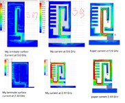
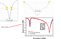
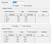
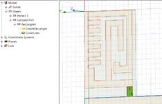
I am trying to simulate dual band antenna from a paper, I get around 90% similar S11, little shift on resonances and also different S11 levels, antenna is working in 2.44 GHz and 5.6 GHz bands, for both bands I get good match radiation pattern and radiation efficiency... the problem is related to the current distribution.. at 2.44 Ghz I get perfect current distribution on the corresponding arm.. and also some current on the laminate surface.. but when I look at 5.6 band, current distribution is totally different on the resonant arm (compare to the paper)regarding the maximum value of the surface current and also there s more current density on the laminate surface and one more thing the S11 bottom at this band is more smother compare to what in the paper is sharp resonance .. can any one explain to me what is different in my situation..!!! I am using HFSS, exciting the model with lumped port .. refer to the attached photos foe currents, S11 and also the simulation setting in HFSS...I am using bigger enough radiation boundaries.... is it the lumped port causing this..!!!!!
I am trying to simulate dual band antenna from a paper, I get around 90% similar S11, little shift on resonances and also different S11 levels, antenna is working in 2.44 GHz and 5.6 GHz bands, for both bands I get good match radiation pattern and radiation efficiency... the problem is related to the current distribution.. at 2.44 Ghz I get perfect current distribution on the corresponding arm.. and also some current on the laminate surface.. but when I look at 5.6 band, current distribution is totally different on the resonant arm (compare to the paper)regarding the maximum value of the surface current and also there s more current density on the laminate surface and one more thing the S11 bottom at this band is more smother compare to what in the paper is sharp resonance .. can any one explain to me what is different in my situation..!!! I am using HFSS, exciting the model with lumped port .. refer to the attached photos foe currents, S11 and also the simulation setting in HFSS...I am using bigger enough radiation boundaries.... is it the lumped port causing this..!!!!!