Continue to Site

Welcome to EDAboard.com

Welcome to our site! EDAboard.com is an international Electronics Discussion Forum focused on EDA software, circuits, schematics, books, theory, papers, asic, pld, 8051, DSP, Network, RF, Analog Design, PCB, Service Manuals... and a whole lot more! To participate you need to register. Registration is free. Click here to register now.

analog high pass filter > 8 poles

Status
Not open for further replies.

el00

Member level 5
Joined
May 27, 2009
Messages
80
Helped
0
Reputation
0
Reaction score
0
Trophy points
1,286
Activity points
2,156
Hello
I need to build an analog high pass filter with a very steep response. Chebyshev 8 poles filter is not enough.
I cannot use digital filters in this application.
Unfortunately all the tables available do not go beyond 8 poles.
Switched capacitors filters are a bit noisy, but I do not exclude them at this stage.
What do you suggest?
I think I need to go to 16 poles, I know that it is a lot, but I need at least understand how it is feasible and how much noise I will inject in the system.
Thank you
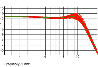
 

Although you did not give a clue of the selectivity, it is unlikely to be able to implement an analog filter in such an order. Consider cascading lower-order filters.
 

TI online filter design tool can calculate higher order filters. Chebyshev filter coefficients can be also calculated with matlab. For steepest transition band, you might prefer an elliptical (Cauer) filter.

Can you give a full pass- and stop band specification to better explain your requirements?
 

Although you did not give a clue of the selectivity, it is unlikely to be able to implement an analog filter in such an order. Consider cascading lower-order filters.
I have no problem In cascading filters, but I do not think I can cascade 2 x 8 poles filters. I don't think it works
 

TI online filter design tool can calculate higher order filters. Chebyshev filter coefficients can be also calculated with matlab. For steepest transition band, you might prefer an elliptical (Cauer) filter.

Can you give a full pass- and stop band specification to better explain your requirements?
I need to have a stopband around 2kHz (to be defined exactly), and a falloff of ~90dB/octave.
Ripple is acceptable, this is not a problem.
Yes I thought about elliptical filter, but I could not find any implementation with such a steep falloff.
 

8th order 1dB Chebyshev gives already around -80 dB at 0.5 fc.
9th order -90 dB.
 
8th order 1dB Chebyshev gives already around -80 dB at 0.5 fc.
9th order -90 dB.
Unfortunately I need at least 90dB/octave, perhaps a bit more. 80 is not enough. How do I implement 9 or 10th order? I have never seen an implementation
 

One significant issue is component tolerances.

Out of curiosity why not a digital filer ?

Here is a single chip solution, you write no code (unless you want to use all the other chip resources, see
right window) -

1596244790414.png


1596244834752.png


Regards, Dana.
 
Unfortunately all the tables available do not go beyond 8 poles.
This statement is far away from truth.
Transfer function of N-order filter consists N-order polynomial. Chebyshev filter uses Chebyshev polynomials, Butterworth uses Butterworth polynomials and so on.

We know how to generate such polynomials. Hint - look for Chebyshev polynomials in the web.

How do I implement 9 or 10th order? I have never seen an implementation

As above, cascade of 1st order or 2nd order well known stages, which poles/zeros following polynomials zeros.
 
  • Like
Reactions: FvM

Hi,

Just to clarify: you may combine a 2nd order with a 2nd order to get a 4th order.
And you may combine a 8th order with a 2nd order to get a 10th order.
But:
The combined cutoff frequency is not the same as the single frequencies.
Example:
When you combine two identical 2nd order Butterworh HP with fc = 1kHz then the resulting fc will be higher than 1kHz.

Klaus
 

if you put an op amp follower between stages, the impedances will be buffered
the stages will not interact
the net result is a higher order filter

so if you combine two identical 2nd order butterworth filters, with the buffer stage between,
the result is a fourth order filter with an unchanged cutoff frequency
 

Danadakk:
I don't like to hi-jack threads, so I will keep this short.
Based on your multiple postings, your knowledge of PSoC seems to be very extensive.

Hopefully you will open someday a thread "PSoC for Dummies"
 

Hi
so if you combine two identical 2nd order butterworth filters, with the buffer stage between,
the result is a fourth order filter with an unchanged cutoff frequency
I don't think so.
Butterworth cutoff frequency is defined at -3dB...independent of filter order.
Even with a buffer: if the first stage is -3dB @ 1kHz ....and the second stage is -3dB @ 1kHz, then it can't be that the resulting filter has -3dB at 1kHz. The resulting will have about -6dB at 1kHz .... and -3dB at a slightly higher frequency.

Klaus
 

the point is not so much where the cutoff is, but an easy way to get higher order filters

the OP wrote about 8th order filters
so if the cutoff has to be ??? Hz, use a design that has a slightly higher cutoff,
so at the desired cutoff frquency, the gain is about -1.5 dB
then the two parts together will yield about -3 dB at the desired cutoff
 

The OP referred to Chebyshev filter, which involves a clear scheme how the transfer function of each 2nd order block should look like. In fact each has individual fc and Q, obtained by decomposing the Chebyshev polynomial. Same procedure has to be performed for other filter prototypes like Bessel or Butterworth.
 

See this 8th order Chebyshev implementation as an example. A 10th or 16th filter has all different pole frequencies and Q.

1596359527750.png
 

Cascading identical stages, effect on cutoff freq -


Attribution : From AAC website (dominant pole stages)

1596361254705.png


Other considerations -


Regards, Dana.
--- Updated ---

Danadakk:
I don't like to hi-jack threads, so I will keep this short.
Based on your multiple postings, your knowledge of PSoC seems to be very extensive.

Hopefully you will open someday a thread "PSoC for Dummies"


I am still learning myself, now focused on the custom onchip component capability,
and learning Verilog. Note you can do customs w/o Verilog by just doing schematic
capture. Verilog of course gives you more control over design.

I do not consider myself an expert, there are however experts over at the Cypress PSOC
website. Cypress now owned by Infineon I think.

The parts themselves a veritable analog and digital breadboard on a chip. And unlike FPGA/ASIC
design the tool, for the most part, eliminates the need to do extensive timing analysis.
Its rare you have to get involved in that. Also lots of designs can be codeless. Either because
you use an example project, like this filter, where code is done for you (primarily DMA setup
code) or ones where you do logic basic design with schematic capture. Even the more advanced
functions there are many APIs for that function so you wind up writing very little code to
manipulate it.

I use PSOC also as a test bed generator frequently to generate stims for other designs because
of how fast one can gen up signals.

I am a fan of the parts :)


Regards, Dana.
 
Last edited:
This statement is far away from truth.
Transfer function of N-order filter consists N-order polynomial. Chebyshev filter uses Chebyshev polynomials, Butterworth uses Butterworth polynomials and so on.

We know how to generate such polynomials. Hint - look for Chebyshev polynomials in the web.

As above, cascade of 1st order or 2nd order well known stages, which poles/zeros following polynomials zeros.
Sorry for replying after such a long time, but I have been traveling and I had some issue so that I could not connect.
I do not necessarily need tchebycheff filter, I can use also other types, however, I was just hoping to see an implementation of a 10 poles (or more). I could not find any reference. I am not saying that it can't be done!

Again, I am not convinced (as I also can read in other posts) that cascading gives the wanted result.
--- Updated ---

One significant issue is component tolerances.

Out of curiosity why not a digital filer ?
Well.. the answer is not simple.
You have to trust me, I cannot, for good reasons.
One of them: I have to acquire N channels in parallel and I cannot have any jitter in between.
 

Status
Not open for further replies.

Part and Inventory Search

Welcome to EDABoard.com

Sponsor

Back
Top