Continue to Site

Welcome to EDAboard.com

Welcome to our site! EDAboard.com is an international Electronics Discussion Forum focused on EDA software, circuits, schematics, books, theory, papers, asic, pld, 8051, DSP, Network, RF, Analog Design, PCB, Service Manuals... and a whole lot more! To participate you need to register. Registration is free. Click here to register now.

analog cmos DC voltage shifter circuit

Status
Not open for further replies.

AllenD

Member level 5
Joined
Aug 7, 2017
Messages
91
Helped
0
Reputation
0
Reaction score
0
Trophy points
6
Activity points
1,193
Hi Team
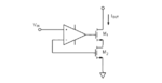
As is known to many people, a common drain circuit can be used as a voltage shifter since it's gain~=1 and the input-output dc voltage is shifted by Vgs=Vth+Vdsat.
It came to me that what if Vgs is too big? If I only want to shift the DC level by 0.5*Vgs, is there a convenient circuit to use?

Thanks
Allen
 

Vgs=Vth+Vdsat.

common source.JPG

This is from Design of Analog CMOS Integrated Circuits by Razavi. The current sink, M2, can also be a resistor. It's not Vgs=Vth+vdsat but Vgs=Vth+sqrt(2Id/uncox(W/L)). From this the minimum difference between Vin and Vout is theoretically Vth.
 
Last edited:

Hi rmanalo
Thanks for the reply. How about the case that I need the level shifted less than that? For example, for a 1.2v Vdd process, vth is normally ~0.4v. This is quite a shift compare to 1.2v. What if I need only 0.2v shift, which is about 0.5 of Vth?

Regards
Allen
 

Hi,

if you want to shift up (increase) signal voltage, then I recommend to use a common source (open drain) circuit. Mind that it inverts the signal logic.

Klaus
 

With enough W and low enough Iload, you can see operation
at VT/2.

You could make a closed loop buffer controlling a common-
source PMOS, but this will cost you bandwidth (but gain
you accuracy / eliminate most voltage drop.
 

Hi Dick_freebird,
Thanks for your reply.
With enough W and low enough Iload, you can see operation
at VT/2.
What circuit are you talking about? common drain? Big W and small I, is the transistor work in subthreshold?

You could make a closed loop buffer controlling a common-
source PMOS, but this will cost you bandwidth (but gain
you accuracy / eliminate most voltage drop.
Do you mean something like the first one or the second one? Or neither? chptr4-f1.png

Allen
 

Attachments

  • chptr4-f1.png
    chptr4-f1.png
    12.2 KB · Views: 202
Last edited:

I would say neither. You connected the input of the OPAmp to a gate. It makes no sense.
 

Hi Frank
Thanks for the reply.
Can you please be very kind and draw the schematic you think it correct?
Thanks
Allen
 

No, I cannot. I don't know what exactly dick_freebird talks about, probably he will explain.
But I show you an OPAmp solution:
<a href="https://imgur.com/IA7QKJ9"><img src="https://i.imgur.com/IA7QKJ9m.png" title="source: imgur.com" /></a>
The DC shift is IS1*R1, arbitrary. You can realize the IS1 with PMOS or NMOS current source, it depends on what you want, to shift up or down the DC level.
 

A resistive divider adds a portion of the supply voltage to the incoming signal. This simulation adds 0.2V.

pot adds 200mV to small signal.png

The signal is attenuated to some degree.
 

Status
Not open for further replies.

Similar threads

Part and Inventory Search

Welcome to EDABoard.com

Sponsor

Back
Top