Continue to Site

Welcome to EDAboard.com

Welcome to our site! EDAboard.com is an international Electronics Discussion Forum focused on EDA software, circuits, schematics, books, theory, papers, asic, pld, 8051, DSP, Network, RF, Analog Design, PCB, Service Manuals... and a whole lot more! To participate you need to register. Registration is free. Click here to register now.

Altium designer 6 ( 3d parts alignment with PCB footprint? )

Status
Not open for further replies.

rocky79

Member level 5
Joined
Sep 20, 2010
Messages
83
Helped
1
Reputation
2
Reaction score
0
Trophy points
1,286
Activity points
1,903
Hello fellows,

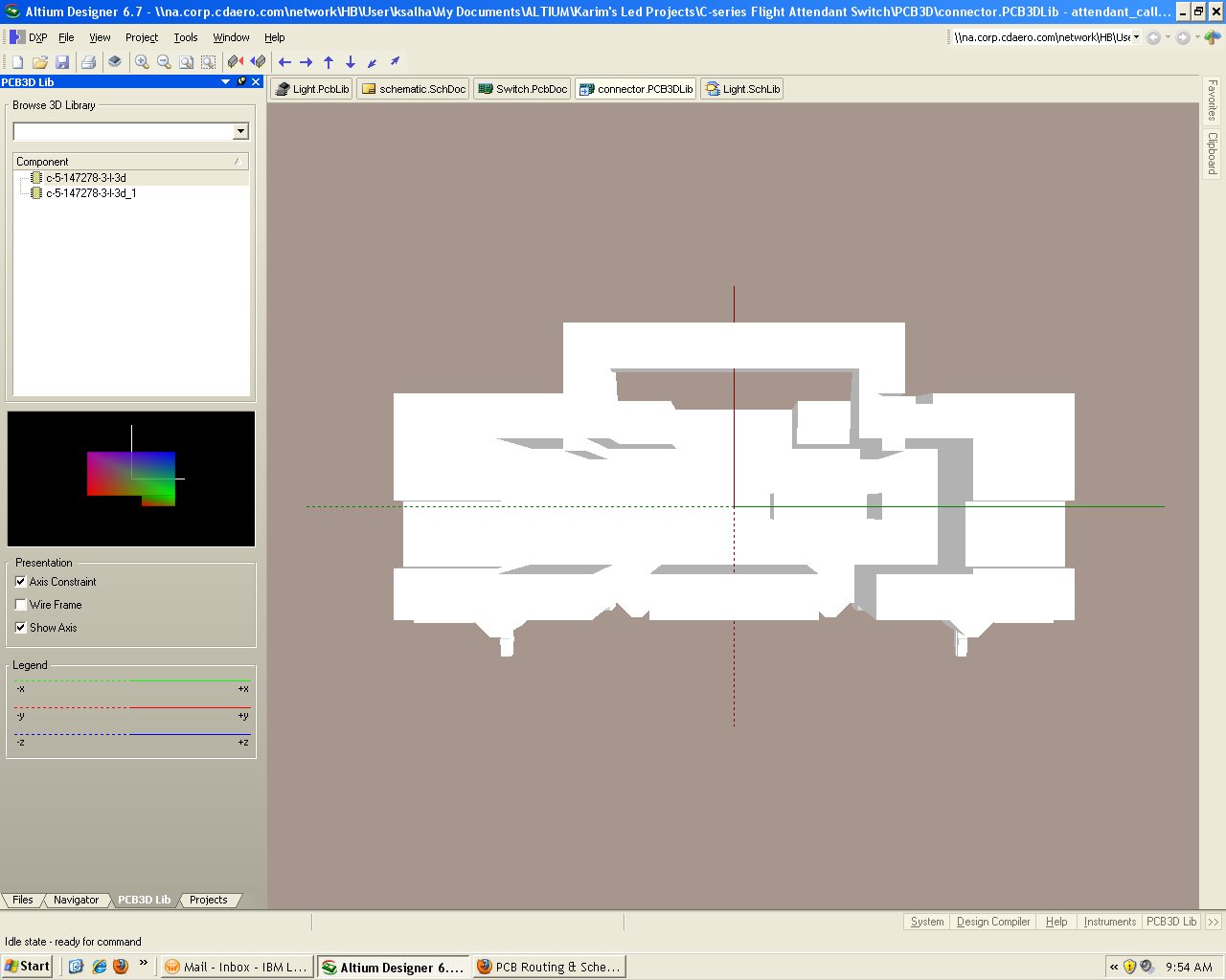
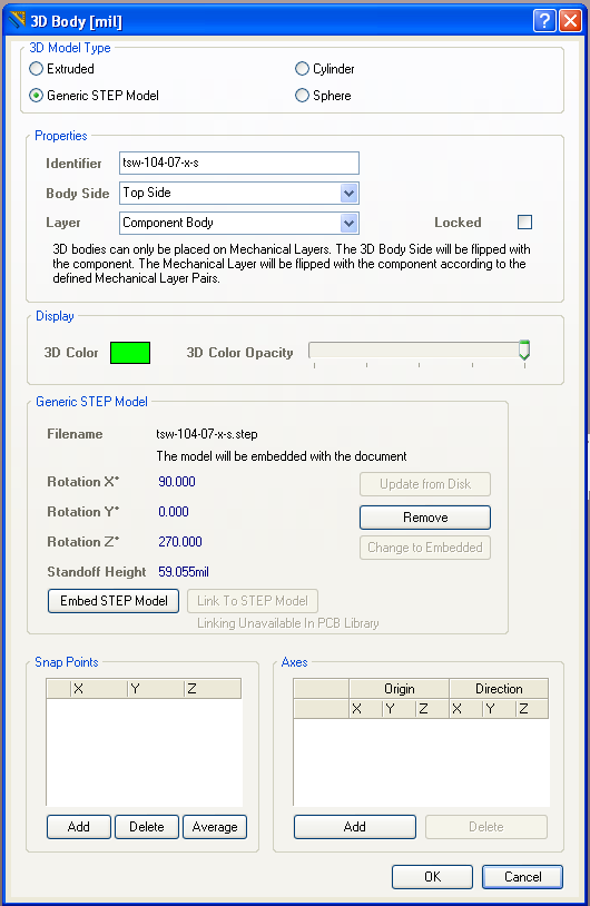
Does anyone know how to align the newly imported PCB3D part with the corresponding PCB footprint? I appreciate your help on this.

Thanks in advance
 

you can add snap points to the imported 3d step model. you will have to be in 3d visual mode to do this.
 

Thanks for the reply. How do you add the snap points? I am looking at the pcb3d view and didn't see any options that let you do this.
 

it's under >>tools >> 3D body placement

if you double click the 3d body it should pop up a property box, where you can add a 0 reference snap point.


I am using altium 6.7 . I don't see that selection. Here is what I have.

pcb3d_tools.jpg
 

Thank you for the effort. I hope someone here knows how to do it.
 

When viewing the footprint in 2D, make sure the layer the 3D body is on is visible. If the part/footprint are symmetric, you should be able to do the math to get the part lined up. If it's off when viewing in 3D, you can select the body and do an Edit > Move > Move Selection by X/Y and incrementally move the part until its perfect. Keep in mind, most of the bodies aren't perfect and close enough is usually, just that, close enough.
 

When viewing the footprint in 2D, make sure the layer the 3D body is on is visible. If the part/footprint are symmetric, you should be able to do the math to get the part lined up. If it's off when viewing in 3D, you can select the body and do an Edit > Move > Move Selection by X/Y and incrementally move the part until its perfect. Keep in mind, most of the bodies aren't perfect and close enough is usually, just that, close enough.

how do I measure distances in PCB 3d mode? I can't see a option that lets you do this in Altium designer 6.7
 
Last edited:

there is a misunderstanding. rocky you are in the 3d library. but if you wanto to add snap point you have to do it in the .pcblib. when you are working in pcblib >>place>>3D Body. then you can add the snap point.
 

Status
Not open for further replies.

Part and Inventory Search

Welcome to EDABoard.com

Sponsor

Back
Top