Vermes
Advanced Member level 4
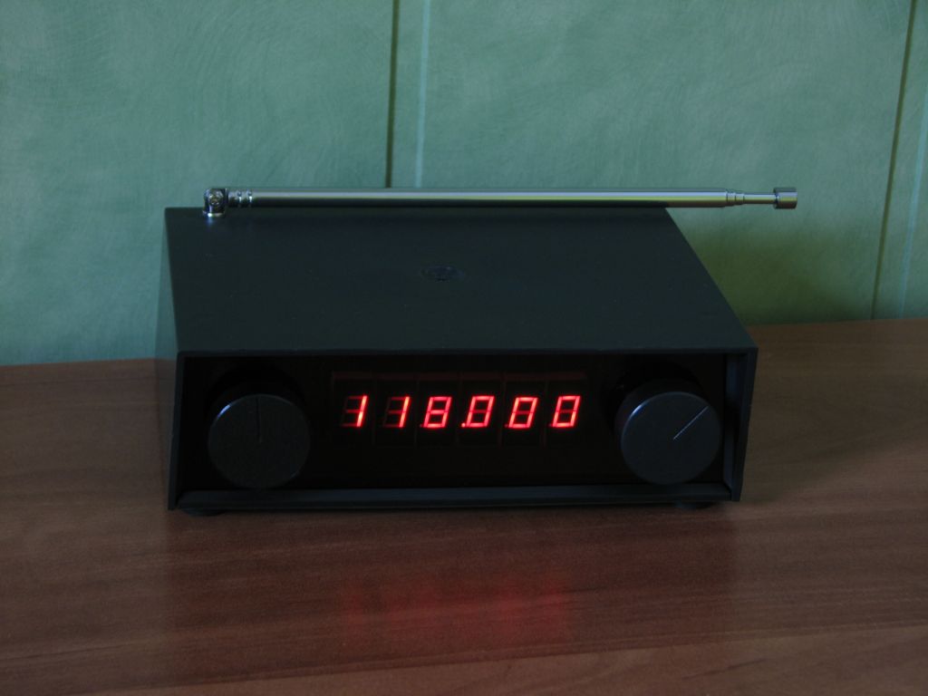
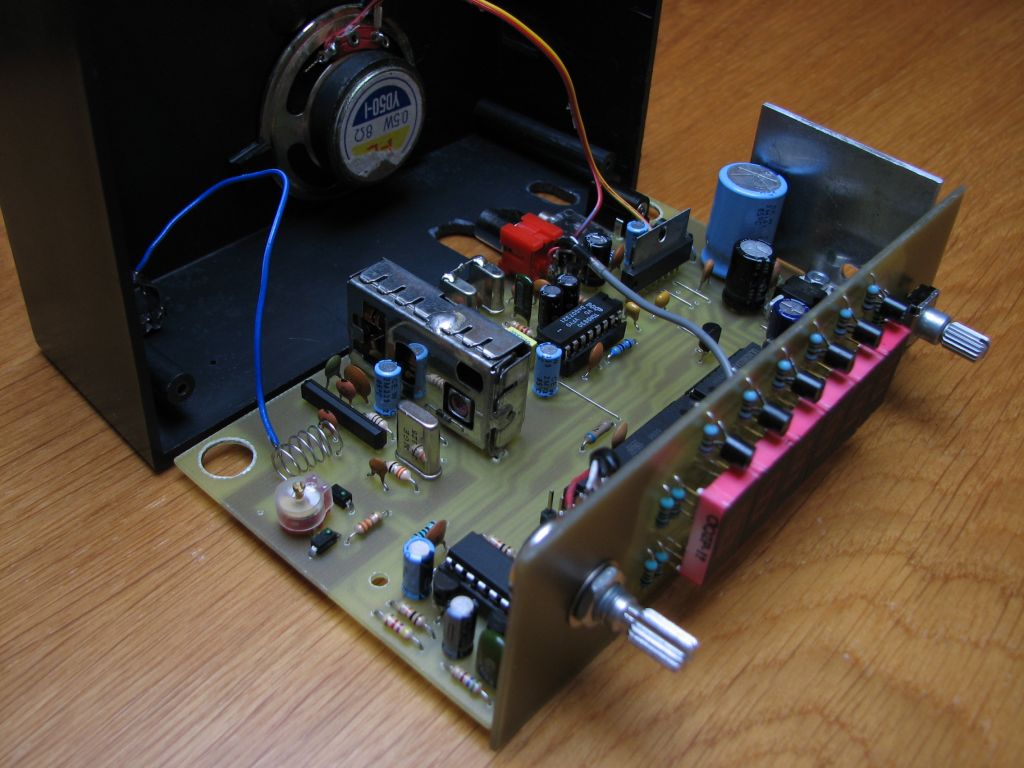
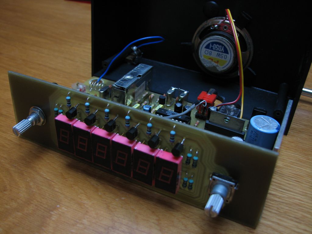
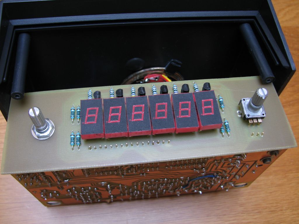
It is a complete construction of Air Band receiver/scanner. It covers the entire frequency range for voice communication in this band, and the received frequency is displayed on the LED display. It also has automatic and manual squelch system. Also an amplifier for direct connection to the speaker or headphones is on the board. The whole can be powered from the switch AC or cigarette lighter socket.
Construction
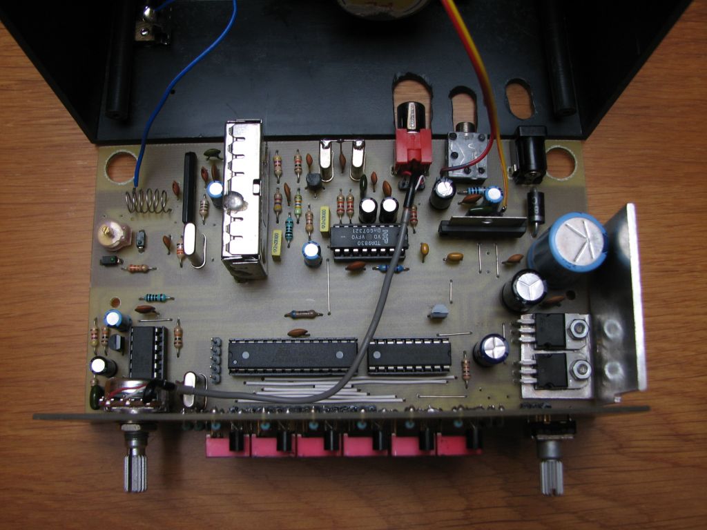
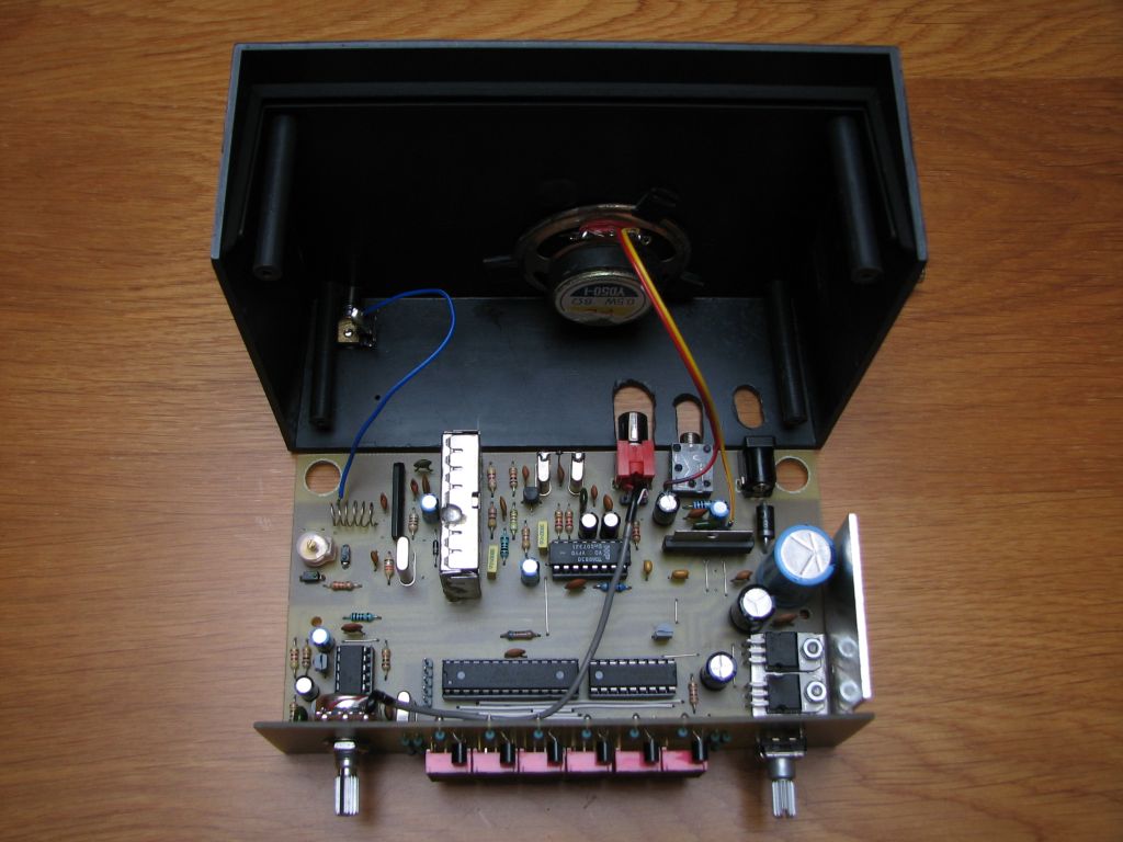
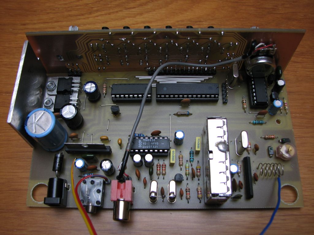
The basic assumption was the use of readily available UKF head. The choice was a small and popular head DT2200, also called GLORIA. Frequencies from the air band that is above the CCIR UKF band, are moved down by the converter built based on the well-known system LA1185. A resonator about 30MHz is needed for heterodyne generator. DT2200 head has a stock of retuning, so it can be tuned in the full range, although this may depend on the particular copy.
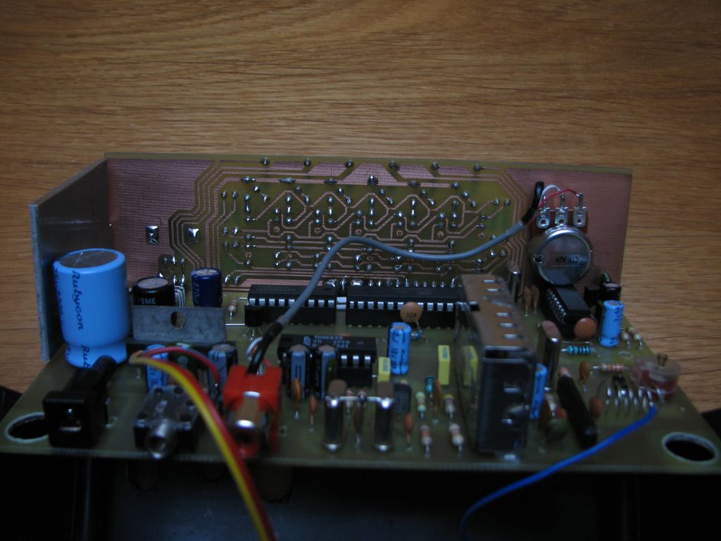
Second, intermediate frequency 10,7MHz is got from the head. That frequency goes through the ladder filter on two quartz resonators 10,7MHz. But then a problem occurs, because so far two modifications were made, and most demodulator AM chips was designed to work at frequencies up to 1MHz. The solution is chip TDA9830. It is an AM demodulator designed for the use in television receivers for demodulating the audio signal in the standard L. This system incorporates an intermediate amplifier running up to 700MHz with integrated ARW system and high quality synchronous demodulator AM. In addition, there is buffer in the system. The buffer is audio signal selector, which was used to build the low-pass filter in the Sallen-Key topology. The audio signal after regulation of the volume, goes to the power amplifier TDA7233S.
The frequency of the second heterodyne is controlled by KIC9256P system. It is a PLL loop removed from a broken car radio. This system is equivalent to the Toshiba TA9256P.
The remaining digital part of the receiver is typical. Atmega88 controls the displays, sends commands to the system of frequency synthesis, reads the state of the pulser and constantly monitors the level of the ARW, which after processing is used to mute the audio signal when nothing is received.
Muting can be done by shorting the audio signal (before the volume regulation) from the synthesis system output open-drain or control the MUTE output of the power amplifier. In the first case we do not get total mute, the second is total, but the amplifier turns on with a considerable delay. The first method was used in the receiver.
Automatic squelch
Since the lack of squelch in the receiver is quite irritating, initially manual squelch system was implemented in the control program. The threshold at which the signal is turned down when only noise is received, is set by the pulse transmitter. But when we want to receive the weak signals, we need to adjust the level. For this reason, also an automatic squelch, known from the newer CB receivers, was implemented in the program. The threshold is continuously and automatically established by the program and used to decide independently when turn off the muting, which ensures a high comfort of using. Its sensitivity can be changed in the control program.
Assembly
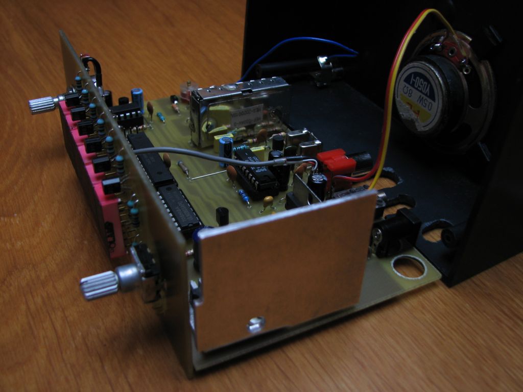
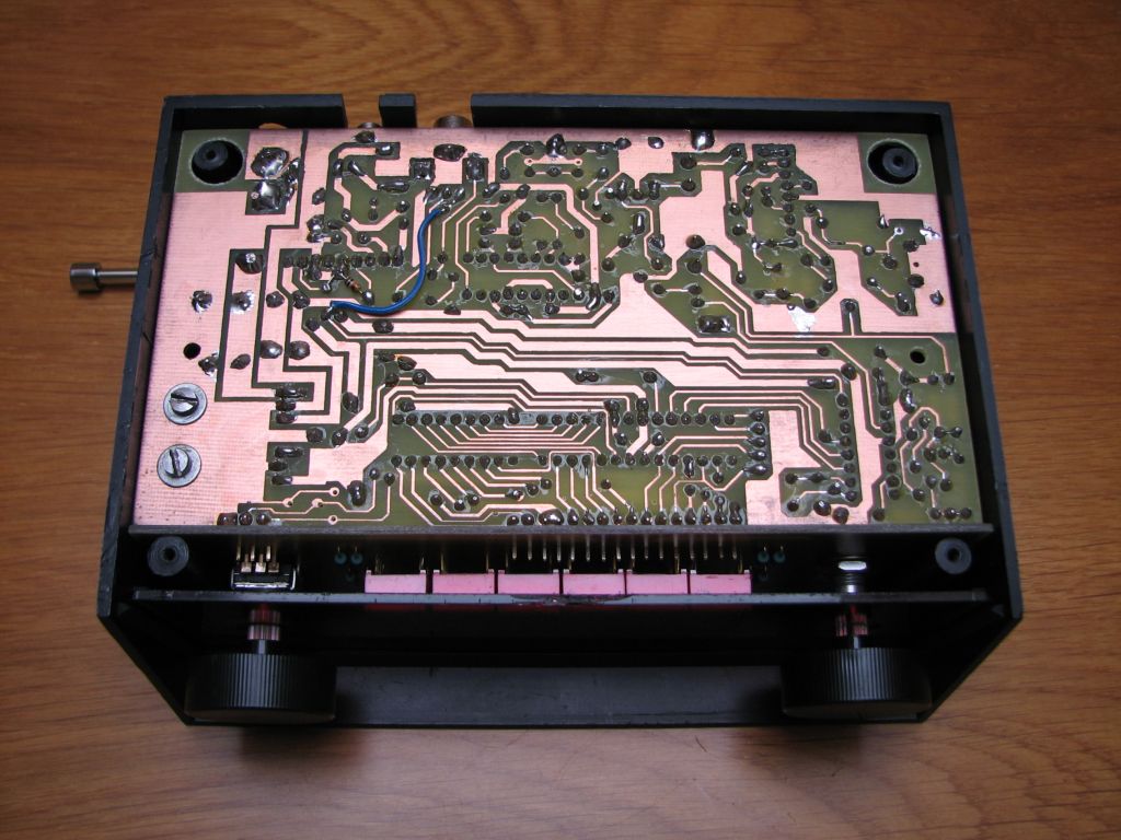
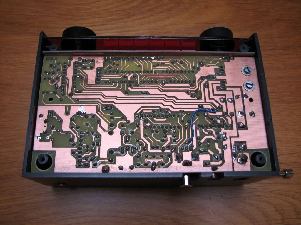
The boards were designed so that all fits in the housing KM-50 with a red filter.
Any resonator of the range 27-32MHz can be used as X1. Its frequency should be totally divided by 25kHz. At the extreme values, the head may not be able to tune correctly. If another resonator than 27,125MHz was used, calculate three values from the following formulas and save the results in the control program file pll.h: PLL_MIN_VALUE = (128,7 - X1_FREQ) / 0,025; PLL_MAX_VALUE = (147,675 - X1_FREQ) / 0,025; PLL_OFFSET = (110,7 - X1_FREQ) / 0,025. A simple telescopic antenna from FM receiver can be used.
Tuning
Only one circuit directly at the antenna has to be tuned. It can be done by ear, but it is better to use squelch. Switch squelch to manual mode and set at the same threshold, when the radio signal is subdued, and then adjust the trimmer so as to unlock the squelch. In this way, it should be possible to find such a trim position, in which a narrow segment of the control, squelch system unlocks.
Link to original thread (attachments) – Odbiornik na pasmo lotnicze