Continue to Site

Welcome to EDAboard.com

Welcome to our site! EDAboard.com is an international Electronics Discussion Forum focused on EDA software, circuits, schematics, books, theory, papers, asic, pld, 8051, DSP, Network, RF, Analog Design, PCB, Service Manuals... and a whole lot more! To participate you need to register. Registration is free. Click here to register now.

Advice on converting a 3,7V battery voltage into ≧ ±12V @ ±1A

Status
Not open for further replies.

David_

Advanced Member level 2
Joined
Dec 6, 2013
Messages
573
Helped
8
Reputation
16
Reaction score
8
Trophy points
1,308
Location
Sweden
Activity points
12,225
Hello.

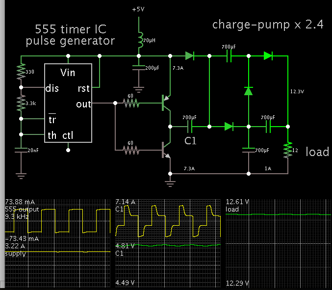
I am looking for a circuit to convert a single positive low voltage(a 3,7V Li-ion battery so 3,2V-4,2V, or 5V) into a symmetrical power supply of somewhere around ±12V while delivering up to at least 1A for each rail.

I find a few simple circuits using different IC's to convert 5V into ±15V but they do never deliver more than around 200-300mA and that is the most powerful circuits, others deliver 70mA or 10mA as two examples.

I would not be sad if it was a isolated output design and in fact I am pondering making that a design criteria, I also like as low a noise as is reasonable since this will be powering analog circuits making measurements that I want to be performed with the utmost fidelity. That is my wish-list at least but any circuit that produces ±12V from 3,7V or 5V is good.

I would also be happy if I didn't need to design my own flyback/forward from scratch so to say, do any one know of any circuit like this that rely on a external pass transistor and not a IC's internal switch?

Or does anyone have any tip about this hole thing in general?

Regards
 

Your 3.7V battery has to provide 7A, if you want to get +12-12 at 1A.
Wattage works out to 24W.

Consider a boost converter for +12V, and a buck-boost for -12V. Then you'll have a bipolar 12V supply, referenced to 0V gnd.

Voltage multipliers are one option but you'll lose several volts through silicon diode drops (unless you can use low-barrier diodes).

If you wanted to wind your own transformer then an efficient topology is a step-up transformer with center tap at the secondary.
 

Well here is a non isolated 3.7v to -12v converter, so ill leave the +12v half to yourself, (you could use the ltc1871 to do that +12vout half)
The simulation here is in LTspice, and shows the -12vout one. (12W)
 

Attachments

  • 3v7 to -12v schematic.pdf
    15.9 KB · Views: 119
  • 3v7 to -12v.txt
    5.1 KB · Views: 78

A switched-coil converter will no doubt work best for you. However just to illustrate, here is a voltage multiplier which uses your 5V supply option. It steps up to 12V, 1A.


The diodes are 300 mV.

The output voltage is not regulated. It varies with load. It will be an effort just to get 12V at 1A, due to parasitic resistance of various components.

A half-bridge is needed rather than a full H-bridge. The H-bridge is more efficient but it produces a supply which is 'floating', without a common ground to your battery. Hence it will not share 0V ground with the -12V supply.

There is the possibility of constructing bipolar +12-12V supplies from a single H-bridge. But again, regulation is absent unless you do some work.
 

Just to add my two yen to the valuable opinions above.

3.7 volts is quite low an input voltage to start with. Unless you are purchasing a state-of-the-art supply, the efficiency will be at most 70%. This will significantly increase the current required from the battery, probably in excess of 10 amps. Your battery run time may be quite short.

If you were to use instead 5v, or better still 2 X 3.7 volt, you will find that it will yield significantly improved efficiencies.

- - - Updated - - -

I did find this unit that will convert from 2.8< Vin <4.0 to 12 volt, and it is 82% efficient, but it is only 0.8 amp

https://www.digikey.com/product-detail/en/bel-fuse-inc/V7AH-01CX200/507-1145-5-ND/679435

Likewise the -12 volt output, but this one would be only 0.5 amp out max.

https://www.digikey.com/product-detail/en/bel-fuse-inc/VRAH-01FX2N0/VRAH-01FX2N0-ND/2258169

However................If you go to an input of 5 volts, your selection is far broader, including a device which will do both output voltages, although only 0.85 amp:

https://www.digikey.com/product-sea...t=0&page=1&quantity=0&ptm=0&fid=0&pageSize=25
 

[Note per David_: Please see following post for revised outlook on project.]

Okey.

I have the option of choosing a 7,2V battery and from what I've read here that sounds as a good change to make?

Also the intent are to lower the output voltage a little bit with linear regulators.
I am a little unsure about what it means that a rail is unregulated, but I would think that using an unregulated rail as input to a linear regulator would create a regulated rail. Well I do know what unregulated is but the question is I guess "how far can the voltage deviate between no load and full load".

This design is meant to be used for a couple of different circuits hence the large output current, but the first circuit it will be used for is a LCRZ-meter that will be able to connect to a PC running Matlab in order to plot frequency vs impedance, the sweep shall go between 50Hz and 1MHz(that is the min/max frequency I have chosen for this meter) but it will be adjustable.

This section of text will start to go a little of topic but about this LCRZ-meter, I also intend to include a optional adjustable DC bias voltage source(which would result in a bias DC current through to test cored inductors and the effect of DC bias on the core and also to investigate the DC voltages effect on ceramic capacitors who's capacitance apparently are heavily voltage dependant.

I had hoped that there would be some solution which would not demand much work to implement(as I have a lot of other aspects of this design to solve) but I am not sure how I would estimate the required current for a LCRZ-meter. The dual supply is intended to make the front end easier to manage, I have seen similar meter designs using single supply and I don't want the hazel that can bring.

But in general you could view the topic of this thread to be meant to produce a sort of standard circuit for me to use when I need a dual rail and only 1 battery. I shall go through all links and suggestions made so far, thank you very much.
 
Last edited by a moderator:

I'm sorry, I had written another response illustrating the system when I realized that I have been going at this the wrong way.
The topic of this thread still applies but I should tell the hole story.

I really want to apologise for this behaviour, it is a effect I believe of my inexperience as well as my confused state of mind, I would feel really bad if this made any of you feel that I have wasted any of you time. I think that what you have written so far will still apply, some of it will definitely apply since it's general knowledge. I would be grateful if you would tell me if this makes you feel I have wasted you time.

So let's pretend that this is my opening post... Kind of...

The "low single positive supply into a higher dual supply" was/are intended to be something I can turn to repeatedly hence the high current(I'm really not sure, even unsure about what kind of currents my soon to be illustrated design could need) while some application would require higher currents and others lower currents.

But I am setting up a situation which will and have started to confuse me(which isn't hard to do, confused is my middle name), so please forgive me if I have asked for something I didn't need(I'm now not sue what I actually need) so let me show you the idea I am trying to realize.
Note that I have been trying to get this design going for quite a while but the battery supply is the first step in the system and I have spent hours scouring the net for solutions but in the end I simply don't know what to do and gives up(for the time being because I am hell bent on finishing this design)

This is the general idea, as you will notice there are 2 ? marks which is signalling that I haven't been able(yet) to acquire insight into how those stages is to be implemented(and they are actually the two hard stages of the design besides the battery/USB stuff:
LCRZ-meter_non-complete_illustration.png

Right now I have neglected to include any hint of the optional DC bias circuitry which in the end will be one of the main features of this LCRZ-meter, I did that because 1, it is confusing enough as it is. 2, I haven't yet worked out how or where the DC bias is to be introduced(it is somewhere inside the large ? stage.
Those two motivations is enough but also I think that I would do good by not including that and complete(more or less) the remaining design first and regard the DC bias as a "Add-on feature" later.
I have lots to keep my mind busy anyway but I am close to have acquired all the knowledge I need about the XMEGA to be able to implement this.

As for the format of this project, I intend to make it into a device which in it's first revision is dependant on the USB communication with Matlab, when that is done and I understand that process I intend to add a LCD and user interface to the device and add firmware to enable it to be used stand alone without the PC connection, using USB to charge the batterie(s) in both cases.

So what am I asking in this thread?
Well at one hand I am asking for your thoughts about the design idea as a hole.
On the other hand I am asking for help with the particular section that is handling the batterie(s) which is the most important motif for this thread and you can ignore the other stuff if you want.

At the very end of this post I will write and link to the devices I have chosen for this design, I put it there because this turned out to be a long post and it isn't necessary for you to know that in order to help me so by putting it last it is intended to be an optional read to those whom are interested(and has the time) to get more involved in the idea of this design.
The only thing you need to know is that I am using a dedicated IC to implement a galvanic isolation of the USB data bus.

So right now I am working with the following questions:
1, how to isolate the USB power supply, enabling the full use of the USB 5V rail(500mA), and if the isolation circuit should alter the voltage in order to suit the battery charging circuit.

2a, choose a battery configuration(what voltage and what number of batteries connected how?)

2b, design a charging circuit for that configuration, I could make things simpler by the use of older battery types but Li-Ion presents such a increase in performance that I really want that type, and it shouldn't be above my head to design that considering all the integrated solutions out there nowadays aimed at Li-Ion charging and monitoring.

2c, what kind of DC-DC converter stage would be suitable to be driven by that battery configuration to produce a higher dual supply rail?

Just because I'll add as a attachment the illustration that made me realize I was going at this the wrong way since it does show what kind of configuration I have been considering.

Here are the parts selected so far:
I am using ADuM4160 to isolate the USB data bus, and need to separately isolate the USB 5V @ 500mA supply and tailor that to charge any batteries in the system.

I am using a ATXmega128A1U, but depending on whether or not the smaller(ATXmega128A4U) also have the QDEC(Quadrature Decoder) extension of the EVENT system I will use that.
XMEGA128A1U is a TQFP-100 package while XMEGA128A4U is a TQFP-44 package.
Both run with 3,3V(or lower but I need 3,3V to be able to run the XMEGA at USBs 48MHz(Note that this is still just 1 option amongst many and it will depend on how I will accomplish the LCRZ measurement).

And I am using the AD9954 "400 MSPS, 14-Bit, 1.8 V CMOS, Direct Digital Synthesizer" to generate a sine-wave of frequencies between 50Hz and 1MHz. It has sweep capabilities built into it and I intend to enable the use of sweeps from frequency x to frequency y(x & y is specified by the user in Matlab) as well as enabling the device to function as a standard LCR-meter(my MASTECH MS5308 can be set to 100Hz, 120Hz, 1kHz, 10kHz & 100kHz) setting the excitation signal's frequency to one of a number of different frequencies sort of evenly spaced between 50Hz and 1MHz.
 

Attachments

  • failed_battery_boost_consept.png
    failed_battery_boost_consept.png
    21.1 KB · Views: 121
Last edited:

This is a complex project, with several sections. You need to make your job easy. During development, you might as well make a bipolar supply, with two batteries, one for positive, one for negative.

You may find it necessary to draw up designs for all possible ways to build the power supply, in order to help you make the decision.

Questions to consider:

* Have you confirmed that your circuitry can safely extract 24W from one LiON battery? (Due to losses you can expect to increase it 20 percent.)

* Are you familiar with charging/discharging guidelines re LiON type? Are you knowledgeable about fire/explosion dangers from LiON type?

* Which factor is important in your design, whether space, weight, cost, etc., and which configuration satisfies your criteria: (a) one battery and multiple boost/regulation, or (b) multiple batteries and few boost/regulation?

using USB to charge the batterie(s) in both cases.

Have you confirmed whether you can get all the charging Amperes you need from a USB port? Typically you only get 130 or 140 mA right off the bat. To get more Amperes, your device may need to negotiate by means of a protocol called Enumeration.
 

A complex project indeed.

My personal approach for such a project is to focus on the circuitry I've enough experience to design myself, and purchase ready made modules or boards for the areas I don't.

Besides the 7.2 to +/-12 volt converter, I would also get a Li-Ion charger module. You will still require firmware to interface to it properly.

I ignore whether the USB port will have the power capabilities to charge large Li-Ion batteries in a reasonable time. Again, you can add a DC power jack, and just purchase an external wall-wart power supply to charge it.


To your question about DC bias;
Many years ago, I used a Wayne-Kerr LCR meter. Even though it was a large desktop unit, its maximum output was 1 amp, if my memory serves me well.
If you required higher current, you could purchase "booster" modules for up to 20 amps each. You could parallel three of those and get 60 amps, all of them controlled by the master LCR unit.
 

I have begun researching Li-Ion charging and have gotten a basic grasp of the requirements while charging, as such I do realize that USB might be somewhat low power but since the µC will communicate with Matlab over USB I would think that Enumeration would have to be a part of it(at least I think that Enumeration is the process of declaring the USB device specifications to the PC?)

Is it a mistake to assume that since the charge rate of the standard charging of Li-Ion cells is 0,5C that an even lower charge rate might be just as good(relevant to the performance of the battery)?
I am not at all but if I assume that I can manage to max out the USB(which means perhaps 450mA to keep a safe distance from the 500mA limit which would shut down the USB for a while right?) then that might be good enough... I wouldn't mind slow charging since this is kind of temporary.

As many of you probably know USB-C connectors are not far into the future, Apple have implemented them and other companies has also started to use the new USB specifications. Granted it will probably be a couple of years at least before I would have access to such a USB connection to my PC but when I do get that the hole question of USB power delivery being to low will effectively be mute. Since the new SB will be able to deliver 100W at 20V if I am remembering correctly what I read about an hour ago.

And as pointed out this is a complex project and by the time the first revision is actually done USB-C may be much more relevant, though want to speed through this step(power supply) as fast as I can and as such maybe I should put the LI-Ion design on the back-burner and use a technique I can wield safely. I have heard about the dangers of fire and explosions regarding Li-Ion but I think I may have a grasp of that(that does not mean I will act as if that where the case).

But as far as I know the charging is very critical in terms of voltage level(if we are talking about 3,7V cells then for coke anode its 4,1V and for graphite anode its 4,2V which needs to be meet very accurately) but all the quirks related to charging it taken care of by the dedicated Li-Ion charging IC that I have jet to pick out.
And then I need a safety circuit to make dead sure that when the battery voltage comes near the level where it it considered to be dead is never reached(the exact level depends on the particular cell and I will read the datsheet very carefully), since last time I wrote in this thread I have read about Li-Ion cells and after having done that I am not at all as positive towards ebay style 7,2V batteries.

If possible I think it would be much more clear cut if I could use 2 single Li-Ion cells with one charging IC each as well as one voltage/discharge monitor each. Since the ADCs in the design is external I have plenty of 12-bit ADCs in the XMEGA µC that could be used for monitoring both voltage and current draw from both cells.

Even though this Li-Ion stuff is important and not an matter to take lightly on I tend to want to set that aside solving my power supply some other way, is that a mistake do you think?
Why I want to do that is because I want to get to a stage where I can start figuring out the two ? marks in the illustration, I had contact with a dude in Germany that had designed a LCR-meter that where helping me grasp the process he used which was very beneficial and resulted in the ADCs being able to work at very slow speeds.
But before I got to grasp anything he became stretched by he's work duties and he has not been up for corresponding through email since some time ago, but I do have he's source code for he's simpler single cell LCR tweezers project as well as he's PCB files(he shares all this on he's blogg which I have been unable to find again...).
So I need some other resource to research to get through this, I had hoped to avoid analysing hi source code which can be very difficult to do.

I have written enough for this time I think now, my head is spinning in any case.

Regards
 

What I was trying to bring forth before was the idea that maybe I could/should save the battery stuff for the next revision, I don't know how others view the word convention of revisions but I plan for multiple revisions of this design in order to ease up on the work load for me.
Actually much of it isn't as much "work load" as "search load" because there are much in the design which I don't know how to design but that I hope I will be able to find out.

So for the first revision I could power the hole thing with a centre tapped mains transformer followed by the usual power supply design that you have seen more times than you can count.

And then when I have a system that works I do a new revision that adds the USB power isolation, battery charger, batteries, battery monitor system and control, and the DC bias option.

I have read about the front-end and about DC bias and the only info I have about it is that a DC bias could be managed and/but it all comes down to designing with passive components to account for quite a few things and it will never be perfect. Even though nothing is ever perfect that passive component design can really screw up the measurement and introduce anything from a rather small error to a major error that would make the design in my view pointless.

As far as the DDS goes, I have chosen to use one very new and more fancier than the ones before that one, mainly a 14-bit DAC(I am pretty much talking exclusively about Analog Devices DDS IC's, I know there are other with even higher resolution that costs many hundreds of USD) this means that that particular part do cost a large sum if we only refer to the cost of the other parts of the system. Okey the USB isolator is an expensive chip as well but in both cases they are worth it and I do get value for the money.

The DDS has built in sweep capabilities and 1MHz is far from the 160MHz that AD9954 can produce(it is capable of producing 200MHz at the very most but the documentation somewhere on AD's site tells you that 160MHz is really all you can expect as above that the fidelity/quality of the output will be pretty much unusable.

I am however quite lost to when it comes to the acquisition of the data, and particularly the phase information, I have never built or been taught anything about timing circuits and thus far I am making the assumption that as long as I can ensure that both the voltage and current are sampled simultaneously I can work with that. Although I do know that I really should sync the sampling to the DDS output somehow.
The DDS chip has an sync out pin that will do the work in part, I don't know what the requirements are exactly but I know that since the XMEGA µC do have an EVENT system that guaranties a predictable time delay(the event system is pretty much very flexible external or internal interrupts that are directly tied into the different peripherals) that means that the syncing of the excitation waveform and the ADC sampling is possible. As an example with the event system I can super easy interface and use a rotary encoder for the user interface through the use of 1 of the 8 event channels. I just tie it to one of the encoder signal pins, set up the event channel for quadrature decoding with a specified timer and then it just works.
So I can have the DDS chip trigger an event that starts an acquisition, as the DDS sync signal is equal to the internal clock frequency which is quite a bit higher than the frequency of the output I think I will have to somehow see to that a event isn't triggered on every sync signal.

So with events I can sync things since it always takes 3 clock cycles from that the event is triggered until it's action is starting(I think) then if I use the USART in SPI master mode I can use a DMA(DMAs does not work with the SPI peripheral for some reason) to transfer the ADC values to the USB for transferring the data.

I am relying on Matlab to explore and teach my self the math behind it, but that is the BIG problem although I do have some material received from the dude I told you about. It pertains to complex numbers which I have learned the very basics of and I have the equations that is responsible for calculating the impedance so I should be able to work that out in the end.
 
Last edited:

Arg...!

I'm not joking when I say that I have been trying to assemble a perches list at mouser.com to buy the regulators and such needed to support the components in the design concept I've shown for more than a couple of months now.

I know what I need in regards of LDOs but I can't make up my mind as to how fancy a regulator I need, ether I buy cheap and have to keep an eye on output capacitor ESD and perhaps load regulation. Or I buy at a almost double price(still below 1USD) and get a regulator with much better regulation and one that work with pretty much any output cap.

Then the question of whether I should go for 1 single regulator that is adjustable or if I should get 1 type for the 5V rail, 1 type for the 3,3V rail and 1 type for the 1,8V rails.
Oh and 2 types for the +-10V rail supplied by the 12V DC-DC converter output.
There will be a series of regulators, the 10V output will feed the 5V regulator which will feed the 3,3V regulator which will feed the 1,8V regulators.

If any one have any thoughts or notes about this I would very much like to take part of them.

I find my self unable to drop the battery supply idea in favour of the mains transformer.

Regards
 

It is not at all a bad idea to use low drop out regulators in all designs. This is particularly important because you will be using battery supply.

It is also good idea to put the regulators in series but remember that the first one will take all the current. For some strange reason (I do not know myself) I do not like personally the series connection of the regulators; I would rather put all the regulators in parallel.

Why the ESR (what is ESD?) of the output capacitors (they are large value electrolytics, right?) important? Anyway you can also use a low value ceramic in parallel to suppress high frequency oscillations, right?
 

I guess you would have preferred to make your project operate on one supply voltage? But you are forced to use certain devices, and that's the reason you need so many different supplies? Your project is likely to devote a lot of space to power supplies, at this rate. You'll also need level-shifting circuits, so devices don't receive overly high or low signals. Etc.

Tip: Avoid combining on the same supply: (a) a device which is sensitive to dips in supply V, and (b) a heavy load which changes abruptly.
 

ESD... Yes that's a typo for ESR.
If you look at the cheapest of LDO's datasheets they very often specify a output cap ESR range, aside from specifying a capacitance value they also require that caps ESR to keep within a certain range. It has something to do with the regulators feedback loop and where the zero(s)/pole(s) ends up being, I don't even know what zeros ore poles actually mean. I can't find any information that clearly tells you about those kind of plots.
All I know is that it is certain relevant for a feedback loops stability.
If anyone has any resources on this particular subject I could really need some direction.

I can also prefer the parallel regulator solution but when you think about the added power dissipation that it can and will bring unless you spend lots of time in designing with switching regulators(which will also require much more space on the PCB) then the choice kind of makes it self for me at least.

I will have to think about and properly design the power supply rails/planes really careful I think to minimize the noise(from the digital parts) in the more sensitive sections of the design.

I will make up an illustration of the supply system which can be discussed.
 

Zeros and poles are essentially the same thing. When they occur in the denominator, they are called singularities and they cause the function to become infinite. Resistance cannot cancel reactance (because they are always out of phase and hence orthogonal) but can affect the phase in a feedback loop. From an engineer's standpoint, it is troublesome to eliminate poles completely but it is often easy to shift them to a place where they matter the least.

f(z)=1/(z-a) has a simple pole at z=a.

roots of a function f(z) are, as you have guessed, called zeros. Algebraic functions have zeros and no poles. We get into problem with rational functions.

- - - Updated - - -

I can also prefer the parallel regulator solution but when you think about the added power dissipation that it can and will bring ...

Total power dissipation will not change; but the distribution of the power dissipation over the various regulators will.
 

If I where to choose to use 2*(2*3,7V) batteries for generating +-12V how would I be charging those?
It's easy to find single cell charger IC's and there are a lot of other options but I don't understand, should I treat each pair of two batteries as a battery pack to be charged to 8,4V(If they where Li-Ion 3,7V's) or is there some way to build a circuit in order to charge each battery individually.
That last option doesn't sound likely but I don't know and I haven't read a lot of datasheets but I am looking.

- - - Updated - - -

At ebay there are a few AA Li-Ion 3,7V batteries with anything from 1000mA/h up to 10000mA/h, I can't be sure and I have never used any of those before but it is almost as I feel distrusting of the adds for those 10000mA/h batteries.

There are 1 add for 1pc 3.7V 18650 9800mAh Li-ion Rechargeable Battery for 1,07EUR, I hadn't noticed that the EUR and USD had become so close to each other in terms of value, though I have no insight into any such economical things.

Is it possible do you think that those figures are accurate at that price?
 

I have been using 4X3.7V 18650 7500mAh for several years in my home flashlight and they are working fine. All of them are with protection.

I do not think you can charge 2X3.7V 18650 in series with (individual) protection but then, frankly speaking, I do not know. But it should not be a problem if they are without protection.

I believe that laptop batteries are charged individually but discharged in series. I opened the HP battery back and saw interesting circuitry that included one on temp measurement.
 

Yes, it is irresistible for us to wish we can make one battery power a 24W project.

Notice you have post #6 telling how efficiency will not be much better than 70 percent. This means your draw could be upwards of 10A (or 37W) from that little 3.7V battery.

Your entire project has to work (or not work), depending on how you keep that one battery charged. I believe you'll find that you're leaving it plugged in most all the time. And therefore you might as well run on house power. (Except if you won't be near house power a lot of the time.)

The world certainly has changed since the day our choices were between a 9V rectangular battery, or 1.5V cells. If we had to have portability, that is.
 

Status
Not open for further replies.

Similar threads

Part and Inventory Search

Welcome to EDABoard.com

Sponsor

Back
Top