shuma394
Newbie level 6
Hello.
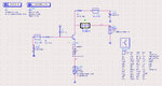
I built a LNA at 300GHz.
so I got 21dB gain (S-Parameter simulation)
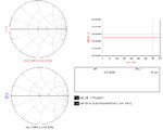
because i want to make a detector, i need a time domain graph.
but LNA didn't work.
so i sweep LNA at 50~400GHz, i got a graph attached.

why there is difference between SP sim and Tran sim ?
how i can solve this problem ??
I built a LNA at 300GHz.
so I got 21dB gain (S-Parameter simulation)
because i want to make a detector, i need a time domain graph.
but LNA didn't work.
so i sweep LNA at 50~400GHz, i got a graph attached.
why there is difference between SP sim and Tran sim ?
how i can solve this problem ??