Vermes
Advanced Member level 4
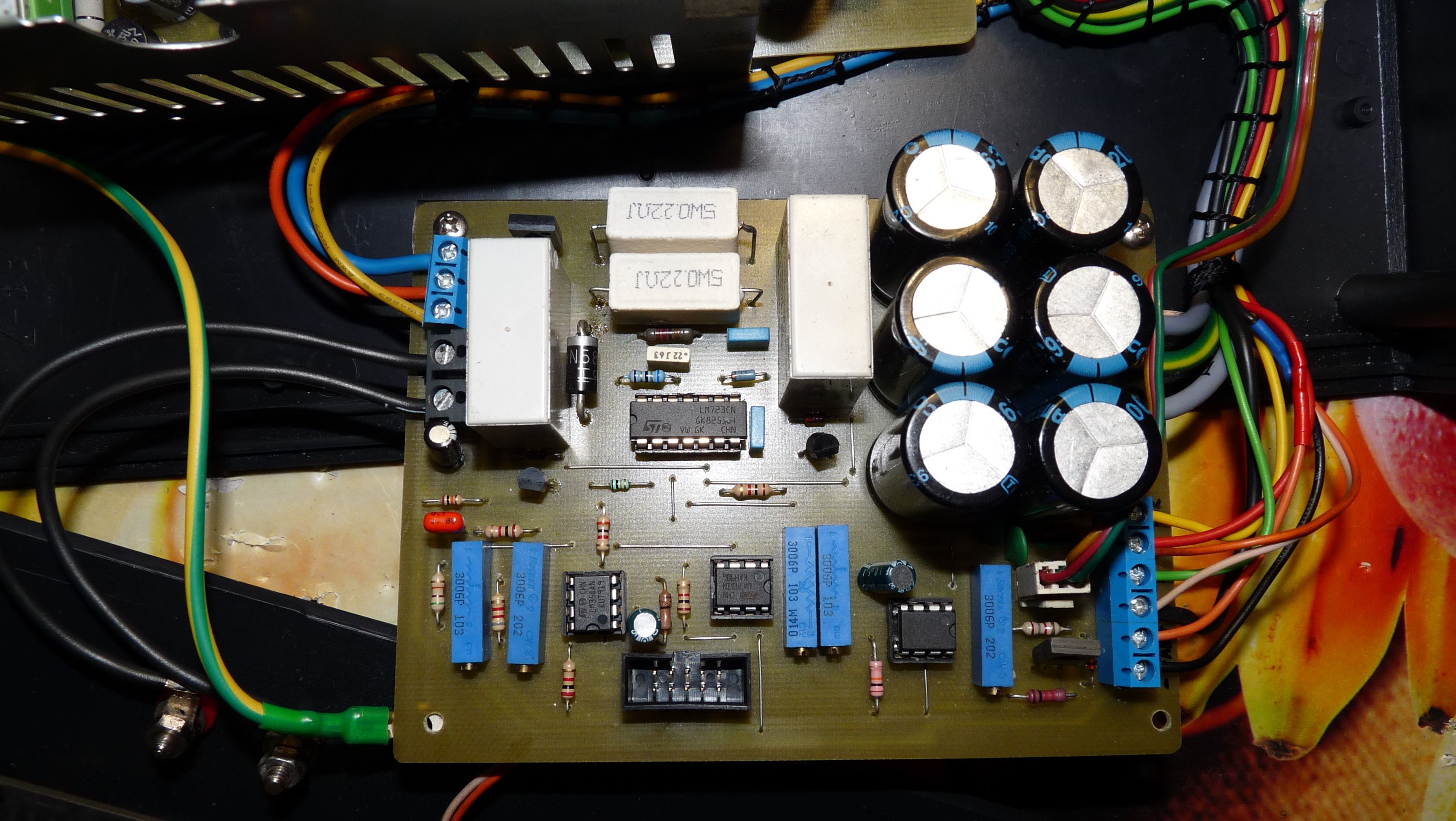
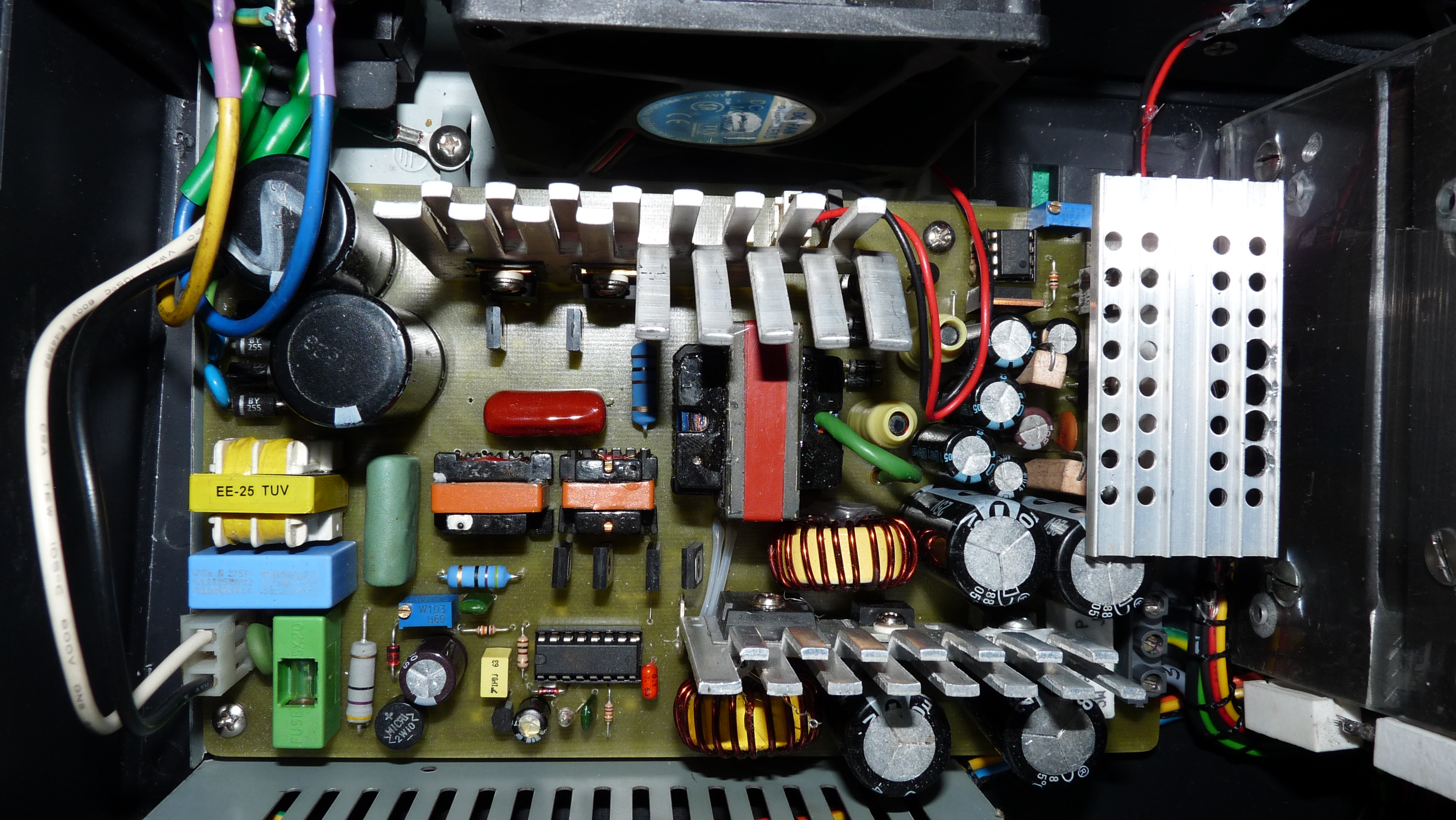
The power supply consists of two separate modules: control part with the stabilizer and the transformer.
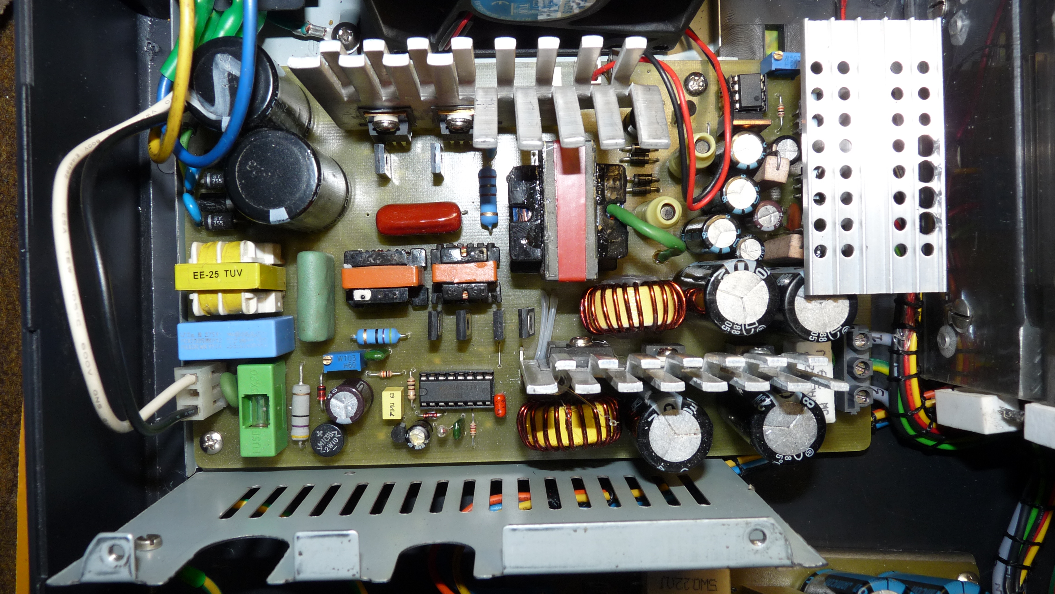
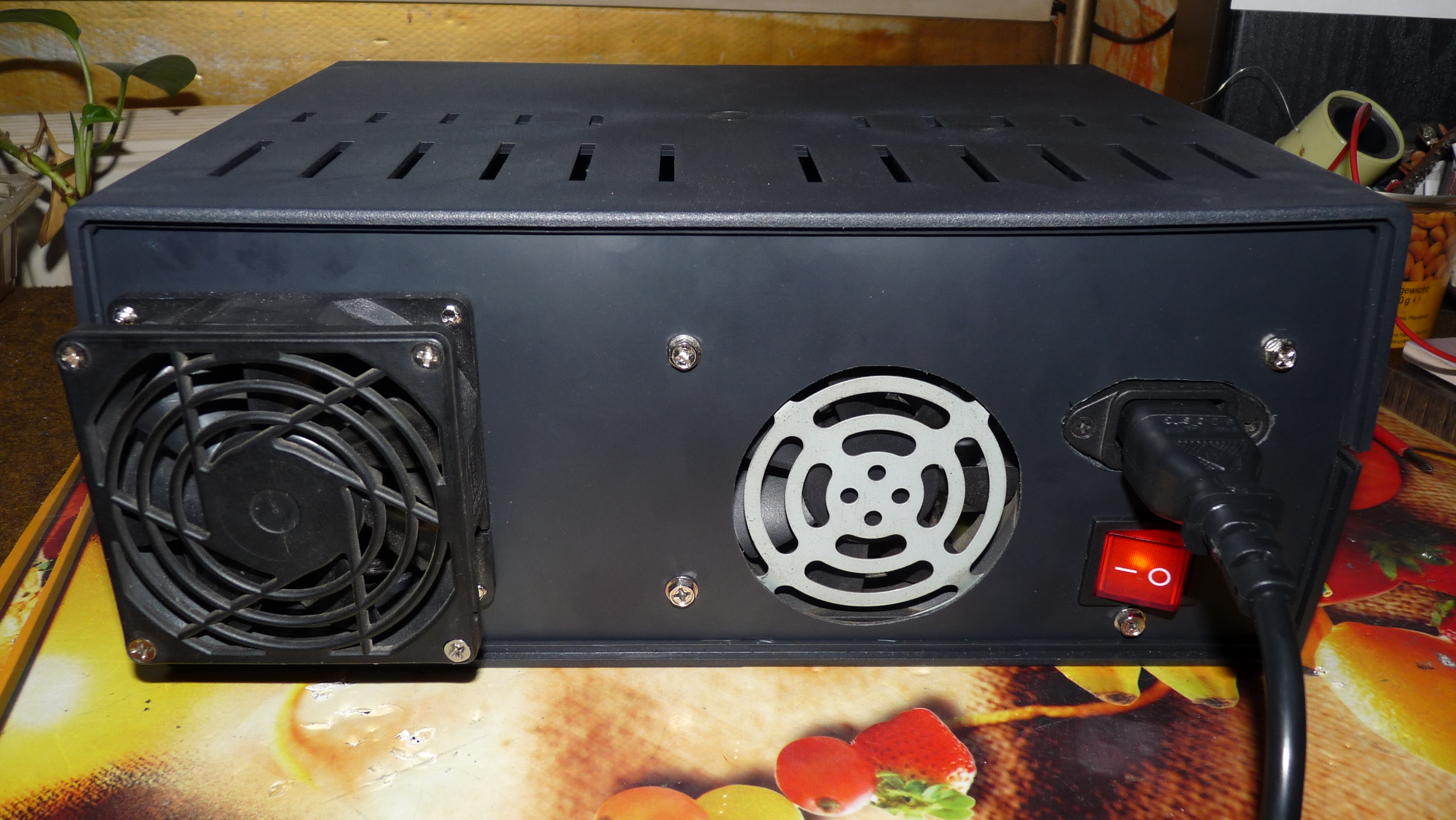
In this project there isn't no power transformer, so its total weight is less than 4kg.
The transformer has short circuit and overload protection and soft start. Support voltage stabilizers and a simple system to control the heat sing temperature were added. The design is simple and cheap, components from old or damaged power supplies AT(X) can be used.
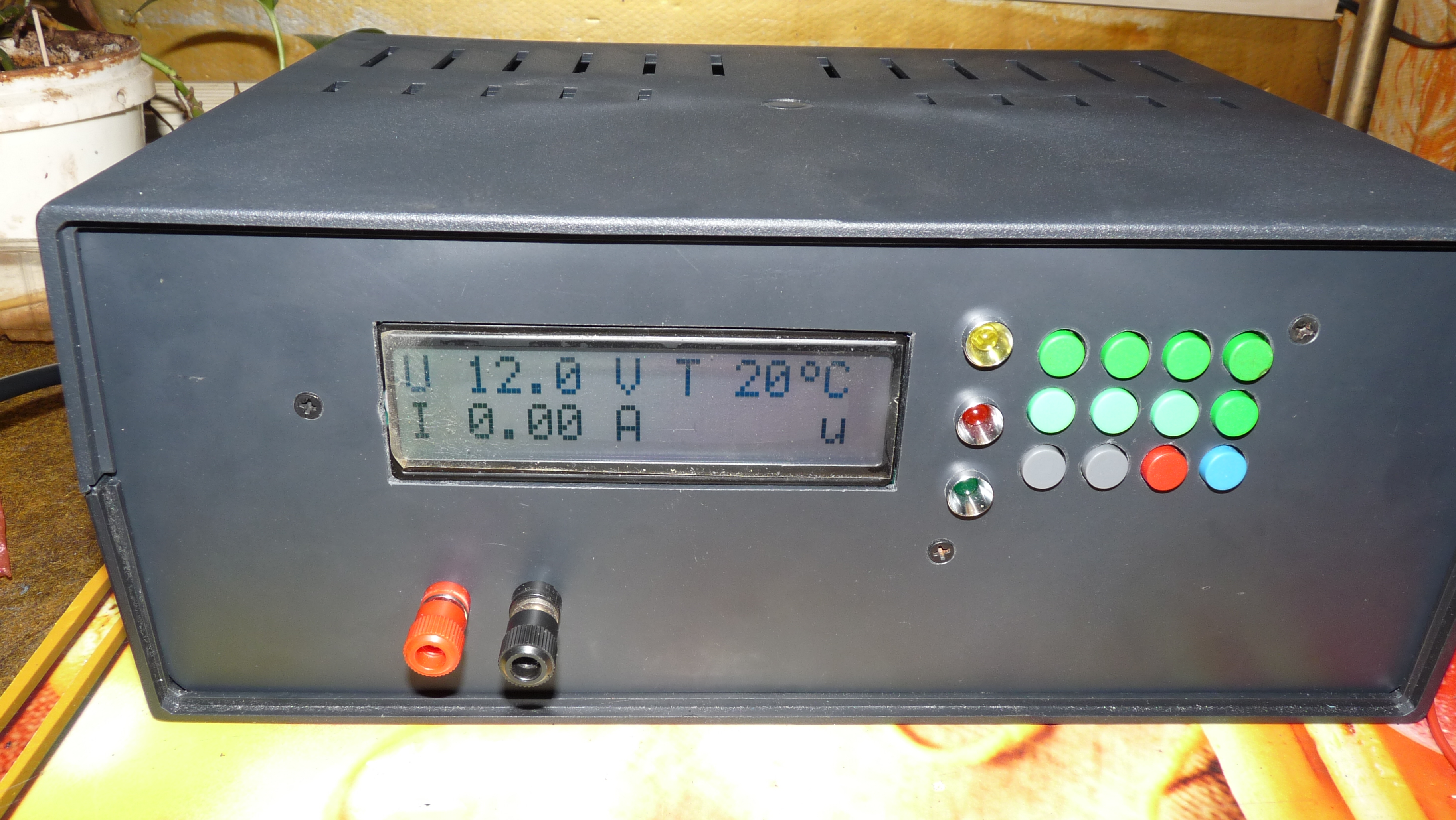
The power supply can be easily supported by the driver. One of previously set voltages can be directly selected or changed by '+' and '-' buttons. Also parameters, speed and stability are good in this device. The power supply has regulation of current limitation.
Parameters of the power supply:
- voltage adjustment range 0...25V
- 100mV voltage control step
- adjustment range of current limit 10mA...5A
- 10mA current control step
- heat sink temperature
- thermal protection
- short circuit signalling
- overload signalling
- function of switching off the power from a powered system
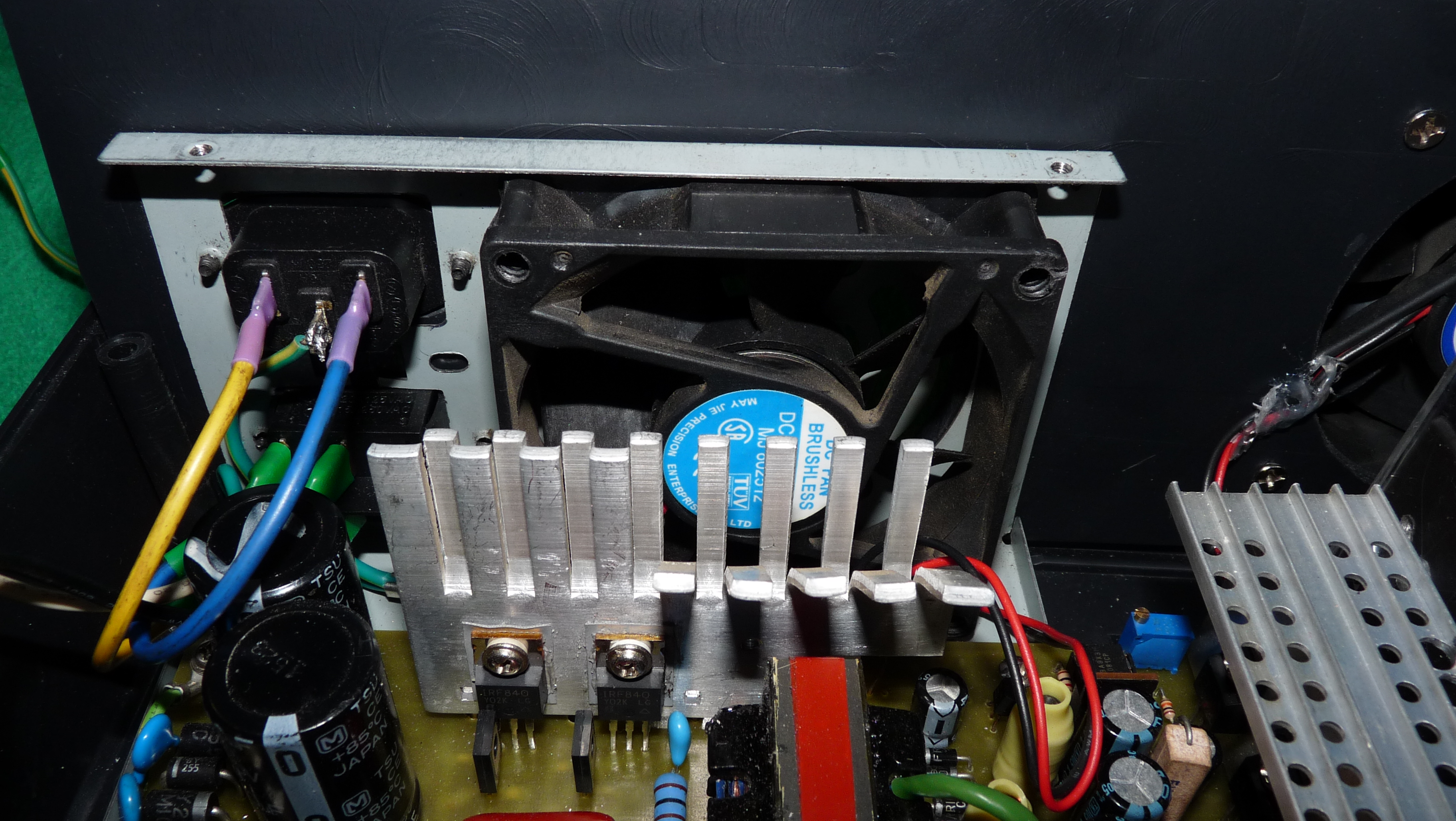
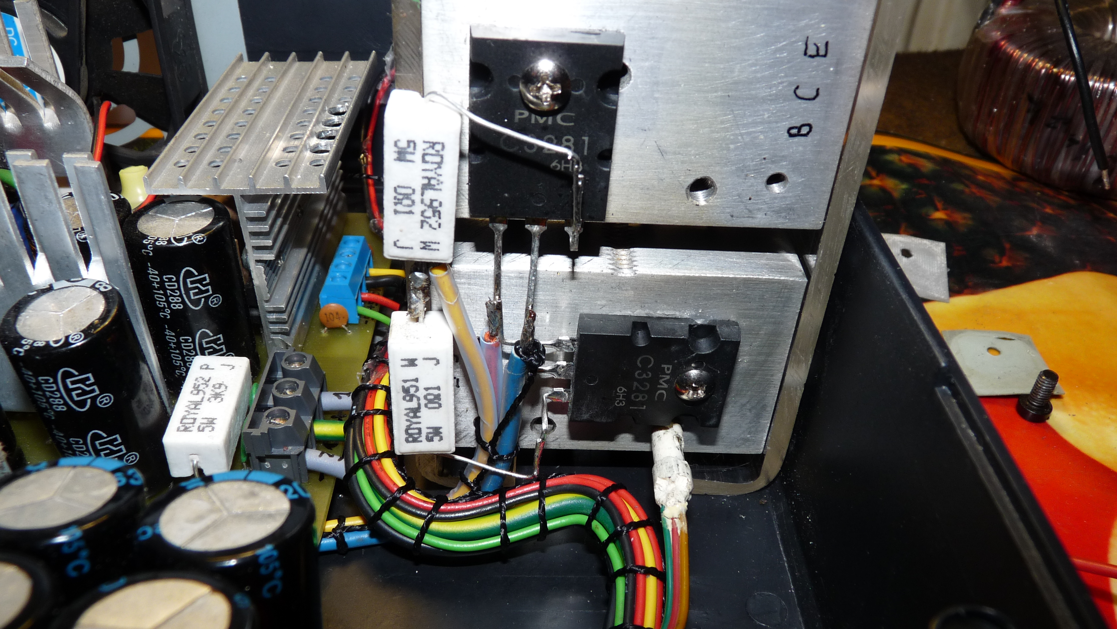
All sub-grades were charged with 4,8A (not to lead to overload) and the voltage drop was 0,2V. The drop was probably due to the use of emitter resistors on power transistors. Separate heat sinks were used in order to eliminate pads under the power transistors. This is necessary, as it turned out during the short circuit tests, to ensure the discharge the temperature from the power transistors in such a short time, that the transistors are not damaged and the load disconnect after exceeding the temperature of 60 degrees Celsius could work. Of course, this temperature can be changed in menu, as well as the temperature at which the fan is activated.
When designing the inverter, it is important to pay attention on one thing: to be stabilized at all sub-grades, 5-6V should be added to drops on transistors. It should be minimum 2x17V to get stabilization.
Link to original thread – Zasilacz regulowany 0... 25V/5A