Continue to Site

Welcome to EDAboard.com

Welcome to our site! EDAboard.com is an international Electronics Discussion Forum focused on EDA software, circuits, schematics, books, theory, papers, asic, pld, 8051, DSP, Network, RF, Analog Design, PCB, Service Manuals... and a whole lot more! To participate you need to register. Registration is free. Click here to register now.

ADC reference Voltage

Status
Not open for further replies.

Thangadurai

Newbie level 4
Joined
Jul 10, 2009
Messages
5
Helped
0
Reputation
0
Reaction score
0
Trophy points
1,281
Location
India
Activity points
1,330
Hi,
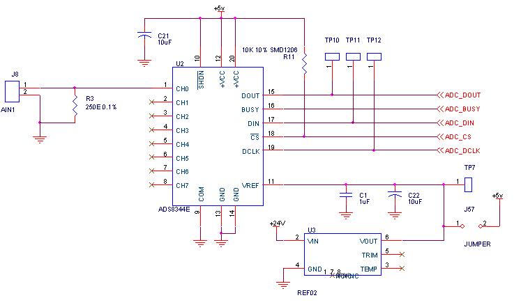
In my application i need to measure RPM from the pulse meter output 4-20ma. i am using ADS8344 16-bit adc and 250 ohm resistor for converting 4-20ma to 0-5v. I am using REF02,5V voltage reference,IC for ADC Vref. I have problem with ADC reference. 1. REF02 ic is getting heat and burned when i connect the pulse meter to adc input 2. i connected the 5V SMPS directly to ADC Vref pin, now ADC is burnned. i dont know what the problem is. please help me to solve this issue.


Attachments

  • adc8344.bmp
    952.7 KB · Views: 61

Did you try applying a current limited power supply(Something like a bench-top RPS) to your Vref and check if the reference input is internally damaged.
 

HI,

as we known PIC is operate at 5V voltage, so may i know if i use the ADC channel,...
can i use the 13V reference voltage which that far exceed the 5v and to interface with the PIC adc channel pin?
 

No you can't, the ADC voltage reference can't be more than the power supply.

Alex
 

Thanks for the reply, then if i wanna detect the 12 volt battery voltage from time to time.....then can not use this method already!
 

If you check the electrical specifications at the end of the data sheet you see

Voltage on VDD with respect to VSS ...................... -0.3V to +6.5V
Voltage on MCLR with respect to Vss ..................... -0.3V to +13.5V
Voltage on all other pins with respect to VSS .......... -0.3V to (VDD + 0.3V)

So it would appear that the maximum voltage you can apply to the Vref pin is VDD + 0.3 volts.

Use a resistor divider to drop the 12 volts.
 

If you want to check a higher voltage you can use two resistors for a voltage divider so that the voltage that goes to mcu is below the specified limit,
for example if you use a 1k resistor from gnd to the ADC input and 4k7 from the input to the 12v then the divider voltage will be 1k/(1K+4k7)= 1/5.7 *12v=2.1v
You can change the resistor ratio according to your needs.

Alex
 
  • Like
Reactions: sysysy

    sysysy

    Points: 2
    Helpful Answer Positive Rating
Hi Thangadurai

After examining your schematic the only concern that I have is that you are powering the ADC from the 5V reference supply circuit.

Generally speaking 5V reference (REF02) cannot source a lot of current (mA is low). You may want to check the source current REF02 is able to provide and then compare that to the current consumption of the ADS8344.

In a good design the ADC is usually powered (+VCC pin) from a DC/DC converter and the (Vref pin) is connected to the REF02.

One solution is to drop the 24V down to 5V using a buck converter and power the ADC using the BUCK but keep the Vref pin connected to REF02.

I hope this post was helpful.
Regard
RR
 

Just be aware that 4-20mA through a 250ohm resistor gives 1-5V not 0-5V
Mike
 

@rrashid and MikehZA

You are answering to the first post in this thread which was about 7 months ago.
The new posts in this thread is #3 and below

Alex
 

For lower current signal,you can easy use sampling resistor,but be sure the input voltage mustn't more than the ADC reference and the maximum input level described in the datasheet.A easy solution is to use resistor to divide.

For upper current signal,a good current transformer is recommedded.There are many various of ratio in the market,such as 100:1,1000:1,etc.

Good Luck!
 

Status
Not open for further replies.

Part and Inventory Search

Welcome to EDABoard.com

Sponsor

Back
Top