Continue to Site

Welcome to EDAboard.com

Welcome to our site! EDAboard.com is an international Electronics Discussion Forum focused on EDA software, circuits, schematics, books, theory, papers, asic, pld, 8051, DSP, Network, RF, Analog Design, PCB, Service Manuals... and a whole lot more! To participate you need to register. Registration is free. Click here to register now.

[SOLVED] active inductor and cap are in parallel, i can't get it resonated in desired freq?

Status
Not open for further replies.

orz

Junior Member level 2
Joined
May 26, 2013
Messages
24
Helped
0
Reputation
0
Reaction score
0
Trophy points
1,281
Activity points
1,440
anyone can help me? Thx!
my active inductor's impedance in 2GHz is 1.103+j*463.194, so you can replace this circuit with a resistance and inductance in series. and the res is 1.103 Ohm with the inductance of 36.86nH.
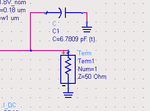
now i put a cap(6.7809pF) on the input port like this:
1.png

the value of cap is calculated according to the rule below:
the admittance of my circuit is Y=jwc+1/(jwL+R), so if i want it to resonate in 2GHz, the imaginary part should be zero.
(note: because the impedance of active inductor changes vs freq, a choose the resonant freq in 2GHz.)

however , the imaginary part isn't zero in 2GHz, Why? please help! Thank you!
2.png
 

What are your design layout factors, distributed capacitance and inductance and Q of filter, source impedance etc. It appears to be very low Q impedance ratio with 50 Ohms
 
  • Like
Reactions: orz

    orz

    Points: 2
    Helpful Answer Positive Rating
Your inductor Q factor is very high, so when converting Z to a parallel equivalent circuit (Y), the inductance virtually remains 36.8 nH (with about 200kOhm parallel resistance).

To get this inductor in resonance at 2 GHz you need about 0.172 pF in parallel at the position where you "measured" the inductor impedance as stated in you posting. I just used omega^2 = 1/(LC).

I assume that you know that actually measuring the impedance curve of such a circuit in a 50 Ohms referenced system is virtually impossible.
 
  • Like
Reactions: orz

    orz

    Points: 2
    Helpful Answer Positive Rating
Code:
Thanks!
I don't know why 50ohm isn't suitable, would you please explain it?
 

If you would measure such a circuit with a network analyzer, the reflection coefficien is soooo high that it will be on the edge of the Smith Chart, close to RC=+1.

You may know that converting reflection coefficient back to impedance has 1/(1-RC) in the formula. When RC = 0.999 (as in your case, a very small relative change in RC will lead to a large relative change in 1-RC.
 
  • Like
Reactions: orz

    orz

    Points: 2
    Helpful Answer Positive Rating
Your inductor Q factor is very high, so when converting Z to a parallel equivalent circuit (Y), the inductance virtually remains 36.8 nH (with about 200kOhm parallel resistance).
yes, but why is 200kOhm in parallel? shouldn't it be 1.103 in series ?
To get this inductor in resonance at 2 GHz you need about 0.172 pF in parallel at the position where you "measured" the inductor impedance as stated in you posting. I just used omega^2 = 1/(LC).
thx! your calculation is right !
but i still don't understand , i calculate in this way :
Y=jwc+1/(jwL+R) , where R is 1.103 Ohm , so C=L/(w^2*L^2+R^2).
what is wrong?

If you would measure such a circuit with a network analyzer, the reflection coefficien is soooo high that it will be on the edge of the Smith Chart, close to RC=+1.

You may know that converting reflection coefficient back to impedance has 1/(1-RC) in the formula. When RC = 0.999 (as in your case, a very small relative change in RC will lead to a large relative change in 1-RC.
your are right, the reflection is very high. but what does "RC" mean?
i didn't get 1/(1-RC) in my formula, how did you get it? I don't really understand it .

Thanks for your help! WimRFP!
 

Sorry for not explaining. RC = reflection coefficient (S11)

Your impedance is given in a series circuit: 1.1 + j463, that means the Q factor of the inductor 421.

Now we will convert this to a parallel equivalent circuit as your capacitor is in parallel. I your capacitor was in series, you didn't need the conversion to a parallel equivalent circuit. I show you the steps how it can be done:

convert to polar notation:
|Z| = 463 Ohms (use Pythagoras) and Arg(Z) = 89.864 degrees { invtan( Im(Z)/Re(Z) ) }.

As your capacitor is in parallel, it is handy to convert your circuit to a parallel equivalent circuit (as you can add Y values for parallel ciruits).

For conversion from Z to Y:
|Y| = 1/|Z| Arg(Y) = -arg(Z): |Y| = 2.160e-3 S, arg(Y) = -89.863 degrees.

Re(Y) = 2.160e-3*cos(-89.863) = 5.13E-6 S, Im(Y) = 2.160e-3*sin(-89.863) = -2.1560e-3 S

The real part of Y is a resistor of 1/5.13e-6 = 195 kOhms
The imaginairy part of Y is an inductor of 36.84 nH (that is your high-Q inductor).

To counteract the imaginary part of -2.1560e-3 S (to get a fully real Y), you need to add +2.156e-3 S in parallel.
To do that you need a capacitor in parallel with |Z| = 1/2.156m = 463.8 Ohm -> 0.172 pF (at 2 GHz).

So at your resonant frequency, you circuit behaves as a real impedance of 195 kOhms.

If you don't like the polar conversion you may say Y = 1/(1.1+j463) and multiply this with (1.1-j463)/(1.1-j463).

If you have a low Q inductor, you will see that after the conversion from series to parellel equivalent circuit, the inductance value for the parallel equivalent circuit will not be the same.
 
  • Like
Reactions: orz

    orz

    Points: 2
    Helpful Answer Positive Rating
Status
Not open for further replies.

Part and Inventory Search

Welcome to EDABoard.com

Sponsor

Back
Top