Continue to Site

Welcome to EDAboard.com

Welcome to our site! EDAboard.com is an international Electronics Discussion Forum focused on EDA software, circuits, schematics, books, theory, papers, asic, pld, 8051, DSP, Network, RF, Analog Design, PCB, Service Manuals... and a whole lot more! To participate you need to register. Registration is free. Click here to register now.

about H-Bridge FET Driver conrol

Status
Not open for further replies.

bosskardo

Junior Member level 2
Joined
Mar 20, 2014
Messages
24
Helped
0
Reputation
2
Reaction score
0
Trophy points
1,281
Visit site
Activity points
1,466
Hi
I came across a H-Bridge FET Driver design where both high side outputs were set high (both high side inputs connect to the same microcontroller pin) when the motor was run in either side. The direction and speed was controlled by giving a PWM to low side input corresponding to the direction.
Why would both high side outputs be set high together, is there a benefit to this?

Thanks
 

This sounds like a stepper motor drive drive where the high side switches just provide a current limited PWM source. Stepper motors need lots of current, and a high voltage to get them to work quickly due to the time constant (L/R) of their coils, the old way was to put a high power resistor in series with them, so you would use a 24V supply to feed a 5V motor, now people use PWM to get the same result.
Frank
 
Hi,

can you show us the schematic?

It seems it needs one connection for both high sides, and two conections for the two low sides. In total three....
I see no benefit in this.

Klaus
 

Actually it a DC motor but I get it now. This way you can apply more power to the motor.
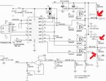
I have another question about the image below. Why are there the marked connections to power supply and ground?
dc h bridge.jpg
 

Status
Not open for further replies.

Similar threads

Part and Inventory Search

Welcome to EDABoard.com

Sponsor

Back
Top