Continue to Site

Welcome to EDAboard.com

Welcome to our site! EDAboard.com is an international Electronics Discussion Forum focused on EDA software, circuits, schematics, books, theory, papers, asic, pld, 8051, DSP, Network, RF, Analog Design, PCB, Service Manuals... and a whole lot more! To participate you need to register. Registration is free. Click here to register now.

ABCD display on 7-Segment

Status
Not open for further replies.

kasamiko

Full Member level 3
Joined
May 23, 2004
Messages
154
Helped
16
Reputation
32
Reaction score
18
Trophy points
1,298
Location
Philippines
Activity points
1,121
Hi,

Anybody has and idea to display character A,B,C,D on 7-segment with 4 individual switches for each character? I'll be using PIC16F84 or 16F628..


Something like the attached image below..


51_1341906457.png


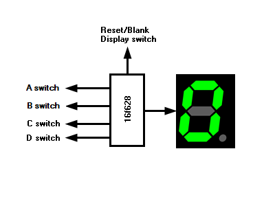
Any idea will be appreciated.


TIA
 

I hate to ask the usual question but is this a college/university assignment? At any rate, you can easily look up the information you need through Google. You'll learn far more finding the information and working it yourself, too.
 

I agree with TonyM.

I'll drop a hint though - forget "abcd" and think in terms of segements on and segments off, it's a simple look up table to convert the input signals to segment control signals.

Brian.
 
no..

my grade school teacher ask me to built this for school quiz bee...;D


BR
 

no..

my grade school teacher ask me to built this for school quiz bee...;D

BR

I'm sure he did it in the hope that you'll learn from the exercise, not just copy someone else's thinking then. Not trying to be unkind :)

Connect the PIC to the 7-seg using direct drive, not multiplexed. You'll find plenty on driving a 7-seg on the internet. Should use a resistor per segment. Choose a resistor value that limits each segment's current to 2mA and try that.

Draw a 7-segment pattern on paper. Then work out which segments should be lit to make each pattern of A, B, C and D. Your PIC must drive these patterns.

Find out and understand what a priority encoder is in digital logic. Consider where you might implement such a function in your software.

The very best of luck, this should be a fun project for you...
 
Other hints:

Make "A" uppercase
Make "b" and "d" lowercase
"C" can be upper- or lowercase.

This is for easy reading. :)
 
I'm sure he did it in the hope that you'll learn from the exercise, not just copy someone else's thinking then. Not trying to be unkind :)

Connect the PIC to the 7-seg using direct drive, not multiplexed. You'll find plenty on driving a 7-seg on the internet. Should use a resistor per segment. Choose a resistor value that limits each segment's current to 2mA and try that.

Draw a 7-segment pattern on paper. Then work out which segments should be lit to make each pattern of A, B, C and D. Your PIC must drive these patterns.

Find out and understand what a priority encoder is in digital logic. Consider where you might implement such a function in your software.

The very best of luck, this should be a fun project for you...


Oh my G0d! I'm already 40 yrs old and my former teacher upon seeing I've been playing with LED's ask me if I can help them make this circuit...


`
 

Spare a thought for those of use who can't even remember as far back as being 40 and still have to work on these puzzles !!!

Brian.
 

Status
Not open for further replies.

Part and Inventory Search

Welcome to EDABoard.com

Sponsor

Back
Top