Continue to Site

Welcome to EDAboard.com

Welcome to our site! EDAboard.com is an international Electronics Discussion Forum focused on EDA software, circuits, schematics, books, theory, papers, asic, pld, 8051, DSP, Network, RF, Analog Design, PCB, Service Manuals... and a whole lot more! To participate you need to register. Registration is free. Click here to register now.

A question related to transistors and power electronics!

Status
Not open for further replies.

meyra31

Junior Member level 2
Joined
May 2, 2015
Messages
24
Helped
0
Reputation
0
Reaction score
0
Trophy points
1
Activity points
209
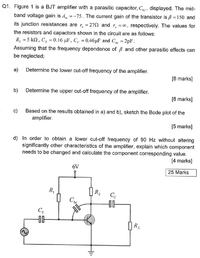
Guys does anyone know how to find R1 from the diagram...

I think to find R2, we can use Gain = R2 n parallel with RL divide by re but how about r1? can anyone solve and post here please?? :)


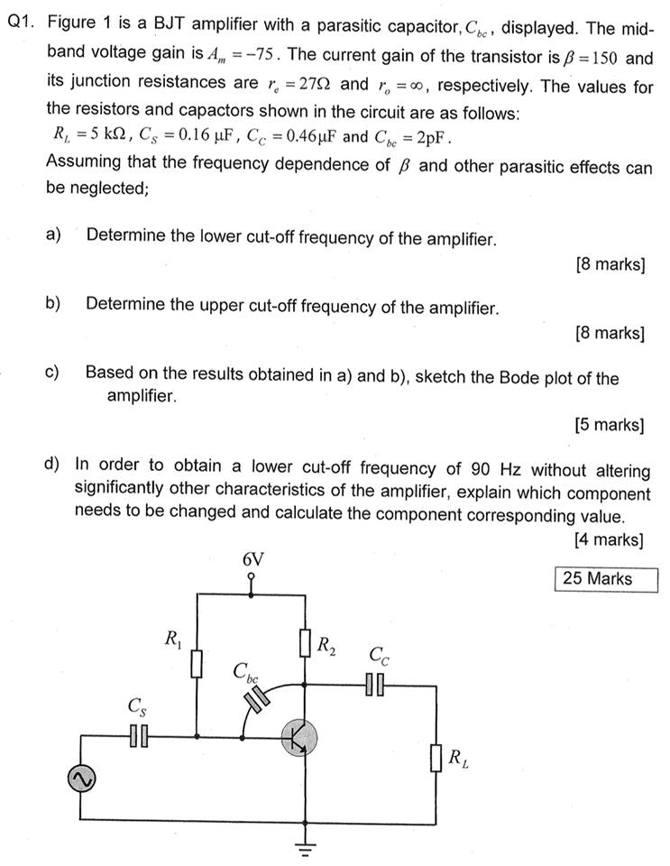
This is the question
 
Last edited by a moderator:

We NEVER bias a transistor like that because one transistor part number has a range of current gain which is also changed when the temperature changes. You cannot buy a transistor with a certain gain. A high gain and hot transistor will be saturated and a low gain and cold transistor would be cutoff.
If you measure the current gain of a transistor and keep its temperature constant (it is difficult because the transistor will be warmed by the current in it) then you can use simple Ohm's Law with the current gain to calculate the resistor values.
 

R1=R2*hfe (gain)*2
It is because the voltage on R1 is about twice the voltage on R2.

Once you know how to do this, microcontrollers will be a piece of cake.
 

apparently there was a mistake in the question.. lecturer said r1 had to be given but thanks anyways mate!
and do you know why the use of a differentria amplifier biased by a current mirror can help to reduce the lower cut off frequency?
 

I don't agree. if you consider a transistor to be "perfect" with an Re connected in series with the emitter. then in a differential amplifier as the two emitter currents are anti phase the voltage at the connection will be zero AC volts, which is the same as when using one transistor and decoupling the emitter. In a single ended amplifier, the input impedance is Hfe time the emitter resistor or collector impedance of the current source so the input RC time constant increases.
Frank
 

Status
Not open for further replies.

Similar threads

Part and Inventory Search

Welcome to EDABoard.com

Sponsor

Back
Top