Continue to Site

Welcome to EDAboard.com

Welcome to our site! EDAboard.com is an international Electronics Discussion Forum focused on EDA software, circuits, schematics, books, theory, papers, asic, pld, 8051, DSP, Network, RF, Analog Design, PCB, Service Manuals... and a whole lot more! To participate you need to register. Registration is free. Click here to register now.

a question about parellel capacitor

Status
Not open for further replies.

will_fung

Junior Member level 1
Joined
Feb 18, 2014
Messages
17
Helped
0
Reputation
0
Reaction score
0
Trophy points
1,281
Activity points
1,435
Hi Everyone,
I have a quesion about parellel-capacitor, if I need 2200uF on the trace, what if I place 10 pcs of 220uF cap instead of one 2200uF?
You know, every cap has ESL and ESR, if I place 10 pcs of cap parelleled instead of one 2200uF cap, the ESL and ESR should get much smaller, and it should perform better. Am I right?
Besides, if I place 10 pcs of cap instead of one 2200uF cap, is there some bad effect except a big space needed?
Thank you.
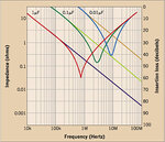
 

If you are dividing total capacitor value equally it will not create a problem. 2200µF capacitor can be divided into 220µF * 10, but if you are mixing different values of capacitors may create ringing effect or distortion.
 

If you are dividing total capacitor value equally it will not create a problem. 2200µF capacitor can be divided into 220µF * 10, but if you are mixing different values of capacitors may create ringing effect or distortion.

HI ,
you mean that if I divide a capacitor into several different value of capacitors, it would cause some problem? such as a 330uF capacitor, divide into 220uF+100uF+10uF, it would create ringing effect or distortion. right?
could you explain more detailed about the ringing and distortion? If the capcitor is used on power trace, is it still create this kind of problem?
Thank you.
 

Every capacitor has a parasitic inductor & series equivalent resistor (Look at the equivalent diagram of a capacitor). Every different value of capacitors are having different ESR & ESL. Even the same value capacitors also has different ESL & ESR value depend on the specification & manufacturer. So the self resonating frequency of the capacitor also vary with respect to the ESR & ESL. So the different self resonating frequency will create noise in the power supply. Even different lead length of the capacitor also create the noise due to the variation in inductance.
If the application area is more sensitive then care must be taken in PCB design itself.
Single capacitor(or same value capacitors in parallel) also will give noise due to self resonance but all the noise waveform will be in synchronous. To avoid this problem we must use a serial inductor, T tilter or Pi filter

www.ultracad.com/articles/esrbcap.pdf‎


Regards
Udhay
 

Attachments

  • Self resonance of capacitors.jpg
    Self resonance of capacitors.jpg
    51.7 KB · Views: 92

you can do it like that ,but you'd better place them together ,if not ,may be introduce some resonance problems.
 

Status
Not open for further replies.

Similar threads

Part and Inventory Search

Welcome to EDABoard.com

Sponsor

Back
Top