Continue to Site

Welcome to EDAboard.com

Welcome to our site! EDAboard.com is an international Electronics Discussion Forum focused on EDA software, circuits, schematics, books, theory, papers, asic, pld, 8051, DSP, Network, RF, Analog Design, PCB, Service Manuals... and a whole lot more! To participate you need to register. Registration is free. Click here to register now.

a question about FIR parallel form implementation

Status
Not open for further replies.

alimassster

Junior Member level 3
Joined
Aug 1, 2006
Messages
27
Helped
1
Reputation
2
Reaction score
0
Trophy points
1,281
Activity points
1,473
Hello friends
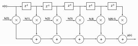
Imagine x as a continuous stream of input samples and y as a resulting stream
the sample delay logic is denoted by Z**-1, where the -1 represents a single clock delay.The delayed input samples are supplied to one input of the multiplier.coefficients (denoted by h0 to h(N-1)) are supplied to the other input of the multiplier Y(n) is merely the summation of a set of input samples.

Now my question

How many clocks do we need to have a result in the output?
And if we need for example N clocks to feed multipliers with N inputs in a N tap FIR filter to calculate Y , then what's the difference between the parallel form and a single MACC based form ( there's an equal delay(number of clocks) in both forms)?
thx
6_1163764296.jpg
 

The no of clocks u need to process this requires what architecture u r using.
a parallel form should give u the output in 2 clocks
input registering----combologic----output registering
1 clk ---- no delay ---- 1 clk

i am telling this in the hardware perspective.
in an fir filter the coefficients are fixed and u don't need to suply them always.
 

a parallel form should give u the output in 2 clocks
input registering----combologic----output registering
1 clk ---- no delay ---- 1 clk


You mean all the inputs are fed into multipliers in just 1 clk? then what about those input delays which take 1 clk each?
 

Z^-1 is a memory delay and it has nothing to do with clock.For example X*Z^-1 means the previous value of x. You must store all the values in memory.

x[t],x[2t],x[3t],x[4t],x[5t],x[6t] ...
 

Thanks coshkun
I read this in the XtremeDSP Userguide that < the sample delay logic is denoted by Z^-1, where the -1 represents a single clock delay > which made me doubtful
seems it's not logical that way caz parallel make no sense am I right?
thanks for your regard
 

Yes,basicly in FIR filter implemention you add the previous values by multiplying them with coefficents.
 

actualy I'm studying different implementations of FIR on FPGA
Have you got any information about semi-parallel implementation?
about Z^-1 delays : How the inputs should be stored and addressed to feed the multiply block?
thx in adv
 

Sorry for the late reply.I don't know much about FPGA implementation.Maybe you need a memory array to store all the values.
 

Hi
u have examples given in the site of the FPGA product u purchased.
these are efficient.
r u doing a filter bank????
 

Hello my friend
that's not exactley a filter bank I'm just studying different implementations such as parallel & semi-parallel forms and the way they are put into hardware which is a Xilinx virtex-4 DSP48 device. I'm confused with the advantages of parallelism
caz I see in parallel form inputs are fed into MUL blocks like a stream and if it's not at the same time , then how is it possible to have an output in each clk?
I wonder if it is by using pipeline in which after some clks that all registers are full , then we have an output each clk.

If inputs are not fed simultaneously , and there is no pipeline , then how parallel differs from a single MACC based form.

thanks for your regard
Have a nice time
GOOD LUCK
 

I'm confused with the advantages of parallelism
caz I see in parallel form inputs are fed into MUL blocks like a stream and if it's not at the same time , then how is it possible to have an output in each cl

one clk depends on ur device resources and the speed they operate on.
check out ur multipliers speed and all.
i think u r using system generator for DSP.
if yes it depends on wat it synthesizes to.
parallel --lot of mul's and adders(N-order of filter)
serail -- one mul and one adder
semi parallel -- a compro between the two.
 

Thank you honey
I'm going to present my seminar on thursday let's see what happens :D
I wish you the best
GOOD LUCK
 

Status
Not open for further replies.

Similar threads

Part and Inventory Search

Welcome to EDABoard.com

Sponsor

Back
Top