Continue to Site

Welcome to EDAboard.com

Welcome to our site! EDAboard.com is an international Electronics Discussion Forum focused on EDA software, circuits, schematics, books, theory, papers, asic, pld, 8051, DSP, Network, RF, Analog Design, PCB, Service Manuals... and a whole lot more! To participate you need to register. Registration is free. Click here to register now.

A basic question on time-domain undershoot

Status
Not open for further replies.

eigenroot

Junior Member level 3
Joined
Feb 1, 2011
Messages
30
Helped
0
Reputation
0
Reaction score
0
Trophy points
1,286
Activity points
1,557
I have a circuit measuring the response of a photoreceiver as follows
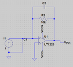
Untitled.png

The photoreceiver can be modeled as a current source and a shunt capacitor (I1 and C1). When I shine a square wave light pulse on the photoreceiver, The output Vout has obvious overshoot on the rising edge, and deep under shoot in the falling edge. But there is no oscillation after overshoot and undershoot.

I am trying to find whether the overshoot and undershoot are from the response of I1, or a result of circuit response (such as C1). Actually C1 is very large, above 1nF. C2 is small compared to C1.

So my question is: what can cause the overshoot (without oscillation) above, and how?
 

The LT1223 is a current feedback amplifier so not a good choice. They don't like capacitance in the feedback path, for one thing. Try a voltage amplifier.

Keith
 

The LT1223 is a current feedback amplifier so not a good choice. They don't like capacitance in the feedback path, for one thing. Try a voltage amplifier.
Keith

Yes - that`s correct. Current-feedback amps need a resistor in the feedback loop that is larger than a certain value that is specified by the manufacturer.
 

In addition, the inverting input of a current-feedback amplifier is a low impedance node and really unsuitable to connect a photo diode. Besides ugly frequency response, you get high current noise.

Even if the photo diode can work with the suggested 1k feedback resistor, you still have a problem with the capacitive load of the inverting input node.
 

In my LTspice simulation of your circuit I saw no overshoot or ringing when C1 was 1nF and C2 was 7pF or greater. With 5pF there was a single overshoot followed by a small undershoot.

But I agree that a current-mode op amp may not be appropriate for your application unless the current from your photodetector is relatively high (0.1mA or greater). Current-mode op amps do have the advantage that they can give good high frequency response with significant capacitance on the inverting node (of which you have a large amount in your circuit). That is because the inverting node is a low-impedance current input rather than the high impedance voltage input of a standard op amp. They also have an output bandwidth that is relatively constant with changes in closed-loop gain (they don't have the standard voltage op amp gain-bandwidth limitation).
 
Last edited:

Status
Not open for further replies.

Similar threads

Part and Inventory Search

Welcome to EDABoard.com

Sponsor

Back
Top