Continue to Site

Welcome to EDAboard.com

Welcome to our site! EDAboard.com is an international Electronics Discussion Forum focused on EDA software, circuits, schematics, books, theory, papers, asic, pld, 8051, DSP, Network, RF, Analog Design, PCB, Service Manuals... and a whole lot more! To participate you need to register. Registration is free. Click here to register now.

90 degree phase shifter

Status
Not open for further replies.

sudip_kuet08

Junior Member level 1
Joined
Mar 27, 2012
Messages
15
Helped
0
Reputation
0
Reaction score
0
Trophy points
1,281
Location
Bangladesh
Activity points
1,401
HI,
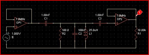
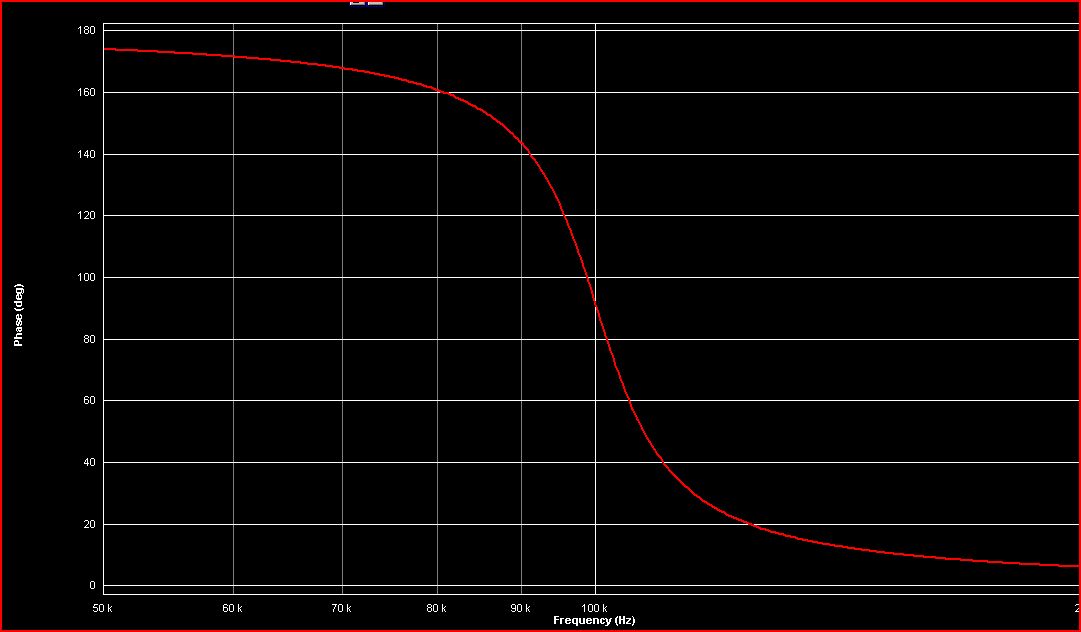
I have to design a 90 degree phase shifting circuit for 100KHZ sinusoidal signal.
The frequency is fixed.
thanks for your time....
 

You will need at least two stages, using either capacitors or coils. Each stage will provide 45 degrees shift.

Or you can make one 40 degrees and the second 50. Or make one 30 and the second 60.

(90 degrees is a maximum amount we speak about, however a single stage cannot give you 90 degrees.)

There are formulas to help you select component values. They use the RC (or RL) time constant.

It may not be easy to measure ohmic resistance in the neighboring parts of the circuit.

You'll no doubt need to fine-adjust either the resistance, or capacitance, or inductance.
 
Dear sudip
Hi
Yes , i'm agree with Bradtherad , but you can use a buffer between your sections ( buffer with op amp ) to earn better result .
Best Wishes
Goldsmith
 

Dear Bradtherad,
Thanks for your help.....it really helped me.
if you please give me an example of one stage and related formula then it will be better for me.

thanks again....
 

Try **broken link removed** for a nice simple circuit with easily adjustable phase shift and very stable gain (with varying R1 and/or C1) around the 90deg phase shift frequency
 
if you please give me an example of one stage and related formula then it
If you use an RC network you'll have : cos teta= R/Z ( series network ) and Z= ((R^2)+(XC^2)) under radical or R+1/jwc
Best Lucks
Goldsmith
 
Last edited:
Thanks to all of you...............

I am going to implement it tomorrow.........


thanks
 

sudip_keut08,

Why not use a resistor in series with a capacitor or inductor? Make the resistance value as low as you can and the reactance as high as you can, and put the circuit across the voltage source. Then the voltage across the resistor is sure to be very close to 90 degrees out of phase with the voltage source.

Ratch
 
Last edited:

Dear Bradtherad,
Thanks for your help.....it really helped me.
if you please give me an example of one stage and related formula then it will be better for me.

The basic concepts are illustrated below. You can adapt one or more to your purposes. Because these are also passive filters, you may need to find a method that does not reduce your signal amplitude too much.

The formula for capacitive time constant: R * C

The formula for inductive time constant: L / R

An internet search should turn up discussions about how to calculate the phase change caused by a given RC or RL combination.

21_1332876693.gif
 

It is very difficult to get exactly 90deg phase using these passive elements. You can make an active phase shifter using op-amps to get exactly 90 deg phase shift.
 
I can u will need to square wave it then back to sine
 

Check Operational Amplifiers and Linerar ICs by David A. Bell. You will find it with name phase compensation circuit..
 
I can u will need to square wave it then back to sine

Sorry, dselec I didn't get you...........will you please explain your logic?

---------- Post added at 09:38 ---------- Previous post was at 09:30 ----------

The basic concepts are illustrated below. You can adapt one or more to your purposes. Because these are also passive filters, you may need to find a method that does not reduce your signal amplitude too much.

The formula for capacitive time constant: R * C

The formula for inductive time constant: L / R

An internet search should turn up discussions about how to calculate the phase change caused by a given RC or RL combination.

21_1332876693.gif


sorry, My post was not so clear I think, let me clarify it............
suppose I have a input signal Vi=A sinwt
I need a output signal Vo=A sin(wt+90)=A coswt


please help me
thanks in advance............
 

Until your latest post it wasn't even clear whether you wanted the sinewave to be advanced or delayed.

The cosine is 1/4 cycle ahead of a sinewave.

Anyway... whether or not this is for a real project...

Here is a phase-shifting circuit which will advance a sinewave in the vicinity of 1/4 cycle. It uses two stages of capacitive current leading.

The resistors to ground are needed to let the capacitors to charge and discharge out of sync. (A similar pattern can be seen in the classic phase shift oscillator.)

The first (input) resistance may be added or it may be present as an output impedance in the preceding device.

Capacitive time constants must suit the frequency of operation.

Time constants are determined by capacitor and resistor values.

My simulation worked with your specified frequency of 100kHz. Values are approximate. Experimentation will be needed of course.

95_1333185160.gif
 

"Quote Originally Posted by dselec View Post
I can u will need to square wave it then back to sine
Sorry, dselec I didn't get you...........will you please explain your logic?"
OK U WILL NEED LTSPICE FIRST
the idea is to get a perfect wide range 90 deg shift is to first design a square wave divider , then if u compare the divided wave to the original wave u will get 80 deg shift.
start using 4013 d flip flop using ltspice and then ill helpthe next step
check out this site..https://www.electronics-tutorials.ws/sequential/seq_4.html
 

Attachments

  • d flip flop 90deg shift.rar
    780 bytes · Views: 107
Last edited:

This All-pass Filter is an interesting phase-shift circuit that can give a phase shift of 0° to 180° (adjustable by R) at a fixed frequency with a constant gain of 1. That output phase varies with frequency and/or the value of R but not the output signal amplitude (at least within the ratio tolerance of the two Rx's).
 
A 90deg shift is easily possible by using an L & C in parallel, and which are tuned to the exact carrier frequency. Choose L & C using old formula 1 by 2 pi root L C. E.g. choose C = 100nF and L = 25.33uH. You can broaden the response by using a lower Q L, or even putting a further resistor in parallel.
 

rohitkhanna,

A 90deg shift is easily possible by using an L & C in parallel, and which are tuned to the exact carrier frequency.

The currents in the L branch and the C branch of a parallel circuit are 180° opposite each other no matter what the voltage frequency is.

Ratch
 

rohitkhanna,


The currents in the L branch and the C branch of a parallel circuit are 180° opposite each other no matter what the voltage frequency is.

Ratch

Thanks Ratch for this totally irrelevant piece of info. Useful but irrelevant.
Here's a circuit outline to illustrate ..
47_1337067731.jpg


And the corresponding phase plot ..
 
  • Like
Reactions: dselec

    dselec

    Points: 2
    Helpful Answer Positive Rating
Status
Not open for further replies.

Part and Inventory Search

Welcome to EDABoard.com

Sponsor

Back
Top