Continue to Site

Welcome to EDAboard.com

Welcome to our site! EDAboard.com is an international Electronics Discussion Forum focused on EDA software, circuits, schematics, books, theory, papers, asic, pld, 8051, DSP, Network, RF, Analog Design, PCB, Service Manuals... and a whole lot more! To participate you need to register. Registration is free. Click here to register now.

8 relay controller on I2c?

Coper

Member level 4
Joined
Mar 16, 2017
Messages
69
Helped
0
Reputation
0
Reaction score
0
Trophy points
6
Activity points
773
I am thinking about how to easily and cheaply control 8 relays (5 or 12 or 24 V) via I2C.
My first choice, I2C port expander PCF8574 and some transistor array. Unfortunately the PFC8574 has a Hi output after reset and NPN darlingtor or N Mosfet array switch relay on during system boot.
Can anyone think of an elegant solution?
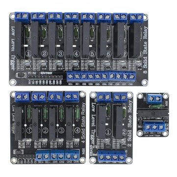
 
there are several port extenders including power drvers.

Have you heared about the 74HC595 shift register? The high current brother is the TPIC6B595.
It can drive up to 150mA / 50V.

I also use the BD8LA700. 200mA / 50V a lot of additional features, but a more difficult to control.

And there are a lot of others.. Just go to a distributor site and search for "relay driver serial"

Klaus
 
Thanks for the idea, unfortunately it's not for the MCU, but for the ARM Allwinner H6 with Linux. A professional board with a very limited number of usable IOs. For me, using a serial shift register means sacrificing at least two more pins and most importantly writing a driver for Linux. The I2C driver is part of the kernel and a number of utilities and libraries are available for it.
I no longer have a free CS signal available for SPI.. I use the I2C bus anyway, so I also need to add a port expander to it .Quite precisely I need to add 8 inputs to limit switches and other switches and 8 outputs to relays
 
Can you not use I2C signals to run such a HC CMOS part? What
are the levels on the board?

You might look for active-low-input, "load switch" parts (maybe
you get lucky and find an octal) and switch the high side with the
relay coils returned top ground.
 
Hi,

have a look at: MCP23018 plus relay driver...
Still we don´t know what current you need for the relays.

Klaus
 
This and an arduino Nano board ? Nano as slave I2C which in turn talks to this board.
Nano a $3 kind of board.


Higher current relays and isolated :


Regards, Dana.
 
OK, I'll clarify
The logic of usable pins on the control board side (including I2C) is +3.3V
Relay
3x 40A SSR +3 to 30V max 30mA
4x mechanical industrial relay pro AC and DC 5V or 12V or 24V, a typical relay coil of this category has power 500mW
1x reserve
It has not yet been decided what voltage will be used to control the relay and the contact, ideally the driver should supply 5-24V current to 8 outputs 500mA max

I would be fine with a solution
PFC8574 or 8575 and TPL7407L Unfortunately, the output of the PCF87x is Hi after the reset, this turns on the TPL7407L and the relay, which must not happen.
inserting 2x 74HC04 between PCF and TPL7407L seems like a complication to me
 
74LS151 is 1-of-8 data selector IC. Input is 3 bits (1 or zero) at 3 pins. As a result it selects one of 8 output pins.

I picture having 8 capacitors, each charged to a voltage usable to power a device or relay during a fraction of a second.

Refresh all caps in rotation several times a second. It depends on how much power each relay coil uses and how much power can come through the 74LS151 IC.

To shut off a device, skip the binary number that activates that pin. The specific capacitor depletes and is no longer refreshed.
 
PCF8574 power on :


1691892226420.png


So use a pulldown on each pin to absorb the 100 uA to maintain a Vol limit
on relay driver board. Then config as outputs with a logic 0 followed by
write.....

Page 7 discusses outputs.


Regards, Dana.
 
As "complications" go, inserting SSI digital piece parts is about the
best wrung out and it also puts another layer of ruggedness between
your core chip and the power switching. You can get small outline
and even single-gate logic parts, which could be handy for routing.
A series resistor and they could drive a NPN with 1mA to get you
50mA of coil current, and surely you can run a relay with that to
handle your 500mA (or 5A).

Virtues include reworkability, price done been compressed for decades
on these generic logic parts and discrete switching transistors, good
package options for however you want to do PCB manufacturing (or
hobby) stuff-n-solder.


Might gate the whole mess with a power-on reset bodge that out-waits
whatever the core chip initialization time turns out to be (provided
you pick a driver that does what it's told and acts benign when
nobody says nuthin'. Make it a "leash" for your debug of power mishaps
too, might as well. You can jumper it later or call it a feature (some people
like belt, suspenders and a real firm wedgie).
 
Hi,

..or use the above mentioned MCPxxx and a bipolar ULNxx. Done.
8 inputs, 8 power outputs...

Klaus
 
Hi,

I had a similar issue. I used an ADG715 connected the "inputs" to 5 V and the "outputs" to 8 low side MOSFETs to control 8 signal relays.

BR
 

LaTeX Commands Quick-Menu:

Similar threads

Part and Inventory Search

Welcome to EDABoard.com

Sponsor

Back
Top