Continue to Site

Welcome to EDAboard.com

Welcome to our site! EDAboard.com is an international Electronics Discussion Forum focused on EDA software, circuits, schematics, books, theory, papers, asic, pld, 8051, DSP, Network, RF, Analog Design, PCB, Service Manuals... and a whole lot more! To participate you need to register. Registration is free. Click here to register now.

5vdc to 3.3vdc options

Status
Not open for further replies.

igeorge

Member level 5
Joined
Oct 31, 2010
Messages
85
Helped
1
Reputation
2
Reaction score
2
Trophy points
1,288
Activity points
1,956
Hello,
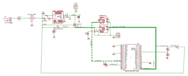
I have to feed 3.3vdc to an esp32 pin.
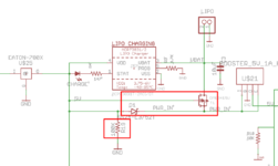
The regular voltage divider will work, but unfortunately I have another resistor already there, R19=100K
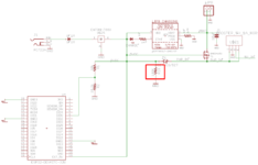
I put a divider, but I am not sure if it will be OK or not, and what to do.
I do not want to use another 3.3 volts regulator.
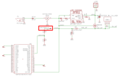
As an alternative, on the second picture I am thinking to put a 1n4148 as isolator.
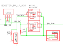
On the pictures, I eliminated 90% of the schematic to make it simpler to read.

What do you suggest ?
 

Attachments

  • GPIO35.png
    GPIO35.png
    26.5 KB · Views: 123
  • GPIO35-1N4148.png
    GPIO35-1N4148.png
    16.5 KB · Views: 130

1) do you know Ohm’s Law? If you put a 28K voltage divider across 100K, it’s not 100K anymore.
2) Why do you need that 100K?
3) why don’t you just replace the 100K with a voltage divider?
4) A diode is not an “isolator”. It’s a diode.
 

The 100 K was part of a different circuit, as in the picture.
 

Attachments

  • 100k.png
    100k.png
    27 KB · Views: 105

Hi,

I agree with barry.

But, why not simply using the 3.3V from pin#1?

Klaus
 

The reason to use in this configuration it is based in what ESP will do or not if powered by outside power.
In the software I have (my own wording).
If the esp it is powered by BATTERY, after a time-out, no push button it is pressed, it will shut the power off.
It is a circuit which receive power from an out pin on ESP, and if the power is ZERO, will shut the power to the whole circuit.
NOW, in case I have the outside power connected, and I do not run on BATTERY, I do not want the shut-down to works.
For this I need an input directly from the 5 volts inputs of the board and not using the 3.3 volts from ESP.
With outside power or battery, I always have 3.3 volts, so no way to differentiate if the board works on battery of external power.
On the picture.
By pressing the PB start, I send 5v_run to ESP.
When ESP starts running, keeps the CONTROL line HIGH.
When I want to stop, I just pull the CONTROL line to ground and NO MORE POWER goes to the circuit.
Zero power consumption on Battery, for example.
 

Attachments

  • Start.png
    Start.png
    16.3 KB · Views: 112

Hi,

I think you are on the wrong way.

As long as you have 5V at the EXT_5V pin (#19), there will be power at the 3V3 output (pin#1).
Thus it makes no difference whether you use a voltage divider directly from 5V or you use the 3V3 out.

You talk about a push-button. We don´t see this in the schematic. Is it important for the discussion?
You talk about "it will shut the power off". We can´t see how this is done.

I´m a bit confused.

Klaus
 
Last edited:

Klaus,
Here it is the difference.
On VIN, regardless what power I put, (battery or outside source), it is always 5 VDC and I will have 3.3 volts on the ESP 3.3 volts pin.
I want to know when the system it is powered from outside source and when it is powered from battery.
I need this info to be present to an ESP PIN.
Then, I will use the software to put the CONTROL line to ZERO(then shut the system power) or I keep the CONTROL line HIGH and the power will be always on the system.
When I press the START button, the G of Pfet will be to ground and I will get 5 volts out from drain.
When ESP gets power, through the software will put high GPIO4 aka CONTROL.
Then G of Nfet will be HIGH- Drain will be low, then G of Pfet is kept low, and latched.
To stop the power on the ESP, I just put the CONTROL line LOW and power will shut down.
If I can get HIGH GPIO 35 when the system is plug to 12 VDC outside source, then with the software i will now to stop the power off timer.
You have a schematic of that.
--- Updated ---

Same principle like here Klaus, but fewer components as IRF7317 is a soic 8
https://randomnerdtutorials.com/lat...off-circuit-esp32-esp8266-arduino/#more-73704
 

Attachments

  • startstop.png
    startstop.png
    11.7 KB · Views: 103
Last edited:

Hi,

This schematic makes more sense now. (I wonder why you didn´t post it before)
Btw: the new schematic is so small one can not detect any details and texts.


Two basic questions before going into detail:
* Why don´t you just put the ESP into deep sleep mode? (no extra hardware needed)
* why don´t you use dedicated power switches?
* did you test / simulate the circuit? I guess you missed the existance of the FET_internal_body_diodes.

I recommend to use a BJT controlled by the very power input using a voltage divider at the input.
The BJT´s collector should be connected to an ESP input with enabled Pull-up.
With this you also avoid problems powering an ESP input while power supply is (temporaroly) shut down.
Don´t forget to use power supply capacitors...

A textual descripions of all your situations (about which power supply is used, when a button is pressed and so on) is rather confusing. Are you able to put this information in a table or sketch a timing diagram with all the signals?

Klaus
 

Hello Klaus,
The circuit it works as is part of a bigger project and I have PCB for it and tested.
If you can read Eagle I can send you the schematic.
I am not good on making a table, but I will try to get the original article where I found the latching circuit.
By the way, on my previous schematic, I do not have a push button, just two pins on the board where I connect the external push button which is called START.
I will see what I can do, but I do not promise.
--- Updated ---

The ON/OFF part of the circuit is better described here
https://github.com/gitpeut/IRF7317-selfextinction
 
Last edited:

Hi,

As far as I can see the circuit in the link has
* not multiple supplies
* has no "power supply detection"
* does not suffer from 5V/3.3V problem
* does not suffer from reverse current through body diode problem

.. or did I see the different schematic?

Klaus
 

Klaus, the attached link was just to show how the stop/start circuit works.
Similar principle works on my schematic.
All I wanted is to get a 3.3 volts detection when the outside power it is connected.
I will put after 7805, an 78XX to get that 3.3 volts.
It is more expensive than resistors, but looks like I have no luck.
Thank you very much for your effort to help me.
Have a great day.
 

Hi,

An additional voltage regulator makes no sense.
You ignore the diodes, you ignore my advice.

So, all I can do is whish you good luck.

Klaus
 

Sorry Klaus, but I did not understand that:
"I recommend to use a BJT controlled by the very power input using a voltage divider at the input.
The BJT´s collector should be connected to an ESP input with enabled Pull-up.
With this you also avoid problems powering an ESP input while power supply is (temporaroly) shut down
."
I am not good on ESP programming.
Can you make a hand schematic using a pull-up resistor?
What value, and connected where ? To the 3.3 volts of ESP ?
 

Hi,

I'm using a tablet without schematic tool.
But it's not difficult:
You need two resistors: 100k and 10k
And you need an NPN bjt, some basic signal type, just what you have by hand.

I refer to your schematic of post#1.
Connect the two resistors in series
* 10k to GND
* 100k to J1_PIN
* Center of resistor string to BJT_base
* BJT_emitter to GND
* BJT_collector to ESP_IO35
That's all hardware you need.
Software
* Now you just have to enable the pull_up at ESP_IO35
* mind that now the signal at ESP_IO35 is inverted than with your solution. It is LOW when power is available, otherwise HIGH.
The threshold is at about 6V input at J1. You may adjust this with modifying the resistor(s).

Finished.

Klaus
 
Thank you, Klaus.
I will do it.
According to Espressif document,
https://docs.espressif.com/projects/esp-idf/en/latest/esp32/api-reference/peripherals/gpio.html?highlight=gpio%20pull%20up
GPIO35 does not have built in a pull-up resistor,
“Only pins that support both input & output have integrated pull-up and pull-down resistors. Input-only GPIOs 34-39 do not”,
so I will just put in the collector a 50 k resistor (Espressif likes to use 50K as built in pull-up resistors) to 3.3volts pin of the chip, connect collector with GPIO35, and change the software for active high to active low.

Thank you very much for help and patience.
 

Hi,

yes, perfect.
btw: well done to read the datasheet about pull up feature. (y)

As an alternative you may use a different pin with integrated pull up feature.

50k should be OK.

This solution has the benefit to draw no battery current. Neither the BJT nor the pullup will carry current during battery operation.
You are still free to use low power sleep modes.
Using Power_off results in 1uA, with RTC running for auto wake up: 10uA.

Klaus
 

Thank you, Klaus, for support.
I will update you if is anything I change.
Have a great weekend.
 

Status
Not open for further replies.

Similar threads

Part and Inventory Search

Welcome to EDABoard.com

Sponsor

Back
Top