Continue to Site

Welcome to EDAboard.com

Welcome to our site! EDAboard.com is an international Electronics Discussion Forum focused on EDA software, circuits, schematics, books, theory, papers, asic, pld, 8051, DSP, Network, RF, Analog Design, PCB, Service Manuals... and a whole lot more! To participate you need to register. Registration is free. Click here to register now.

3GHz DAC SFDR

Status
Not open for further replies.

Ans5671

Member level 2
Joined
Jan 7, 2021
Messages
45
Helped
0
Reputation
0
Reaction score
5
Trophy points
8
Activity points
259
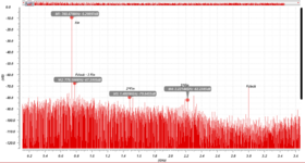
I am simulating a DAC at 3GHz. The SFDR for different frequencies is as follows.
@ 100MHz = 67 dB
@ 700MHZ = 52 dB
@1.47GHz = 60 dB

I do not understand why the SFDR drops for middle frequencies. I have attached the graph for reference.
The Fclock - 3 * Fin amplitude is more than the 3 Fin. Why?

The spectrum is taken for 4096 clock cycles and 4096 * 128 point FFT of the transient output.
Thank you
 

Attachments

  • Screenshot from 2021-07-10 15-54-09.png
    Screenshot from 2021-07-10 15-54-09.png
    81.9 KB · Views: 160
Last edited:

Probably aliasing. If I was you, I would perform FFT to fclk/2 and even consider to apply some LPF after DAC with cut off frequency no higher than Nyquist.
 

Probably aliasing. If I was you, I would perform FFT to fclk/2 and even consider to apply some LPF after DAC with cut off frequency no higher than Nyquist.
Fclock - 3Fin - is clearly an aliased tone. What I do not understand is how can aliasing increase the amplitude?

Performing FFT to Fclk/2 folds back the spectrum to Fclk/2. FFT beyond Fclk/2 shows the complete spectrum beyond Fclk/2 to which one can apply a filter that will give you the truncated version of the above. Even if you filter the aliased tone would be present. Reconstruction filter doesn't prevent aliasing.
 

I wonder how the FFT plot can extend beyond fclock, which is as I presume the sampling rate. Raises doubts about the setup.

As SFDR is relating the fundamental to the highest spurious component, its frequency dependency can't be easily predicted, various effects add to the final result.
 

I wonder how the FFT plot can extend beyond fclock, which is as I presume the sampling rate. Raises doubts about the setup.

As SFDR is relating the fundamental to the highest spurious component, its frequency dependency can't be easily predicted, various effects add to the final result.
That is because the spectrum of a signal is not limited to Fclock. The spectrum extends from -infinity to +infinity. That is where filters are used to reduce the spectrum to the bandwidth of interest and that is why aliasing and folding back of frequency components and noise takes place. MAybe you can read up on the fundamentals of FFT to understand it better.

In circuits, the dominant spurs are not a result of random action. It could be a harmonic distortion component/ intermodulation component, alisaed signal etc. These occur because of specific components/reasons which can be clearly explained. The research effort goes into reducing that dominant spur.
 
Last edited:

That is because the spectrum of a signal is not limited to Fclock. The spectrum extends from -infinity to +infinity.
The statement makes no sense for a time discret signal. The spectrum has a principle frequency range of -fs/2 to +fs/2 repeating periodically.
 

The statement makes no sense for a time discret signal. The spectrum has a principle frequency range of -fs/2 to +fs/2 repeating periodically.
The output of a DAC is not a time-discrete signal. It's analog in nature - a continuous-time, continuous amplitude signal. Hence, the FFT is not taken for no. of clock samples, instead for a value 100x times the clock samples.
 

It is true the output of the DAC is continuous, especially after some filtering. But the DAC does not generate its output signal. It is what you put in as digital code. And you can't put in more than fs/2.
 

It is true the output of the DAC is continuous, especially after some filtering. But the DAC does not generate its output signal. It is what you put in as digital code. And you can't put in more than fs/2.
Agreed.
 

On the theme of having a continuous output - it is actually zero-order held output, I'm sure you know that, which replicates the input spectrum and sinc shapes it. But at the output of the DAC you don't have sampling anymore, so no folding will occur. You can filter and thus limit the frequency content.
 

On the theme of having a continuous output - it is actually zero-order held output, I'm sure you know that, which replicates the input spectrum and sinc shapes it. But at the output of the DAC you don't have sampling anymore, so no folding will occur. You can filter and thus limit the frequency content.
You are talking about an ideal case with zero-order hold pulse shaping at the output. Sure, no problem with that.


But if you look at the system practically, it ain't ideal. And here I am designing a chip that would be taped-out and used for an application. There are plenty of reasons at the circuit level to cause non-linearity - finite settling, mismatch, timing skew, noise etc which result in non-linear components at the output, namely Harmonic distortion. Which if you do the math would fall within the signal band if you just take the FFT up to Fclk/2.

Also, taking an N-point FFT where N-equals no. of clock cycles would only take into account discrete points periodic with Ts interval. But one needs to account for the non-linear settling in the output waveform and hence ~N*100 point FFT is plotted.

And yes, by filtering you can surely remove components lying beyond Fs/2 but what about those that lie within your signal bandwidth and corrupt your spectrum. You need to work at the circuit level.

And this you would know if you have designed a DAC IP. You can help me in that case. Thank you.
 

Yes, sure, you have all kinds of junk at the output. In other words, it is still a zero-order hold but with all the non-idealities added. And I agree with your thoughts about the fft. The procedure of doing the FFT means you effectively sample the output, that's why you are better off doing fft with high number of points which is effectively oversampling and less junk folding back.
 

And this you would know if you have designed a DAC IP. You can help me in that case. Thank you.
I agree with your reasoning overall wrt your method for acquiring the spectra. But it's still unclear why you expect SFDR to trend in a simple manner vs frequency, or why you think the 3*fin spur should be larger than the fclk-3*fin spur (especially when fin is such that 3*fin > fclk-3*fin).

And what's with the huge spur just above 3*fin? That seems like the elephant in the room IMO.
The big elephant you are talking is the image of the input frequency, whose strength is given by sinc(fin/fs). It is systematic and you cannot do anything about it (except filtering of course), unless you change the pulse shaping.
--- Updated ---

There are two mechanisms by which the fs-3*fin gets generated in a DAC.

1. The analog third harmonic of the input signal (after digital-analog conversion) can beat with the clock signal or its leaked signal and create the fs-3*fin tone. This is very trivial. And in this case, you expect the fs-3*fin to be equal/lower than 3*fin in this case.

2. This is the non trivial case, where the fs-3*fin gets generated as phase harmonic before the digital-analog conversion takes place, i.e in the digital data path where the input data is buffered, latched at clock and all. If the supply is not ideal for the digital processing logic, then this could happen, But in your case, since you are at reasonably high fs (of course the technology node matters to say what is high or low), you will have poorer switching in your digital data path, which is identical to having some series resistance on the digital supply. Hence fs-3*in gets generated.

I guess cleaning up the digital data path should help.

And about the SFDR dropping at mid frequencies, I guess it strongly depends on the architecture of the DAC, as in whether it is current source DAC going to opamp, or terminated with resistor load, or a RDAC with opamp load etc. Would be hard to comment on that.

Please let us know if you are able to understand the fs-3*fin issue.
 
Last edited:

Status
Not open for further replies.

Part and Inventory Search

Welcome to EDABoard.com

Sponsor

Back
Top