Continue to Site

Welcome to EDAboard.com

Welcome to our site! EDAboard.com is an international Electronics Discussion Forum focused on EDA software, circuits, schematics, books, theory, papers, asic, pld, 8051, DSP, Network, RF, Analog Design, PCB, Service Manuals... and a whole lot more! To participate you need to register. Registration is free. Click here to register now.

<3500vac HiPot for 240VAC Flyback

cupoftea

Advanced Member level 5
Joined
Jun 13, 2021
Messages
1,880
Helped
45
Reputation
90
Reaction score
88
Trophy points
48
Activity points
9,630
Just reviewing a 12Vout, 10W Flyback for 240VAC/415VAC input.
Must also withstand 458VAC for when "loss of neutral".

Fsw = 60kHz
Fet vds = 900V
Core is EF12.6 (E13/7/4) but bobbin has no added "platform" to make it survive 3500VAC Hipot test.

The transformer spec says its HiPot test was "1.5kV/5mA/1s"

.....Never seen this low test voltage used for txformer on 458VAC (649Vpk) before. Usually AYK its 3.5kV and for 1 min.

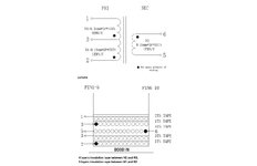
Primary is just 156 turns of 0.15mm enam copper wire
Secondary is just 18 turns of 0.35mm enam copper wire.

No margin tape and no triple insulated wire used.

Its a non isolated design, pri and sec to the same ground. Not aware of the regs for this?
 
Last edited:

cupoftea

Advanced Member level 5
Joined
Jun 13, 2021
Messages
1,880
Helped
45
Reputation
90
Reaction score
88
Trophy points
48
Activity points
9,630
Why is it that a non isolated offline 240VAC flyback doesnt need a HiPot test of 3500VAC?
I mean, a diff mode transient of 6kV+ could hit it...and end up giving output overvoltage?
 

Easy peasy

Advanced Member level 6
Joined
Aug 15, 2015
Messages
4,301
Helped
1,348
Reputation
2,696
Reaction score
1,741
Trophy points
1,393
Location
Melbourne
Activity points
23,998
a flyback running offline, i.e. off the line, or mains is by definition - isolated - and would need to meet the safety isolation specifications of the country of sale

this would often be 2500Vac pri to sec for 1 min
 

mtwieg

Advanced Member level 6
Joined
Jan 20, 2011
Messages
3,758
Helped
1,302
Reputation
2,610
Reaction score
1,348
Trophy points
1,393
Activity points
28,737
1.5kV/5mA/1s sounds about right for a production hipot test, not a dielectric strength type test. Odd for the datasheet to mention that though. Should at least mention which standard(s) it's designed/certified for.
 

cupoftea

Advanced Member level 5
Joined
Jun 13, 2021
Messages
1,880
Helped
45
Reputation
90
Reaction score
88
Trophy points
48
Activity points
9,630
a flyback running offline, i.e. off the line, or mains is by definition - isolated -
Thanks, sorry i should have said , this flyback needs the neutral carrying through to sec side, so its half wave rect and no isolation even though flyback.

So given its non isolated would it ever need a 3500VAC/5mA/1sec hipot test?...i would have thought yes, because a diff mode transient could still hit it?
 

FvM

Super Moderator
Staff member
Advanced Member level 7
Joined
Jan 22, 2008
Messages
51,003
Helped
14,633
Reputation
29,542
Reaction score
13,742
Trophy points
1,393
Location
Bochum, Germany
Activity points
291,794
Transients will never apear between primary and secondary winding if both share the same ground. Diff mode transients are mostly absorbed by the DC bus capacitor. Also it's only functional isolation, failure involves no risk of electrical shock, no hipot test required.

Apparently I'm not the only one who overlooked the reference to non isolated operation in post #1. "HiPot test" in question seems to refer to safety standards, but they don't apply here. We have similar non isolated supplies e.g. in home appliances with grid connected control circuit. Internal DC bus isolation is designed for the working voltage without overvoltage margin.
 
Last edited:

FvM

Super Moderator
Staff member
Advanced Member level 7
Joined
Jan 22, 2008
Messages
51,003
Helped
14,633
Reputation
29,542
Reaction score
13,742
Trophy points
1,393
Location
Bochum, Germany
Activity points
291,794
The peak voltage between transformer windings is limited by switching transistor breakdown voltage, e.g. 600 - 1000 V. In so far 1500 V is reasonable for routine test. Safety standards require basic insulation inside power circuit if failure can cause ignition of fire. In this case transformer HV test can be required. If other protection means like fuses prevent it, HV test is optional.
 

mtwieg

Advanced Member level 6
Joined
Jan 20, 2011
Messages
3,758
Helped
1,302
Reputation
2,610
Reaction score
1,348
Trophy points
1,393
Activity points
28,737
In the standard I'm most familiar with (IEC 60601-1), using the transformer in a non-isolated design does not change the requirements regarding creepage/clearance/insulation, AFAIK. Unless some other means of protection are employed.
 

FvM

Super Moderator
Staff member
Advanced Member level 7
Joined
Jan 22, 2008
Messages
51,003
Helped
14,633
Reputation
29,542
Reaction score
13,742
Trophy points
1,393
Location
Bochum, Germany
Activity points
291,794
Please notice that clearance/creepage requirements are in IEC 61010-1 chapter 6 "protection against electrical shock", not applicable for non isolated circuit because no accessible part is involved. Transformer is completely inside "hazardous part". Refer also to figure 4 for principles of isolation coordination. Paragraph 9.2 mentions possible basic insulation requirement for fire prevention.
--- Updated ---

A transformer with connected primary and secondary should be treated as autotransformer, IEC 61558-2-13 can be applied.
 
Last edited:

cupoftea

Advanced Member level 5
Joined
Jun 13, 2021
Messages
1,880
Helped
45
Reputation
90
Reaction score
88
Trophy points
48
Activity points
9,630
Thanks,
As can be seem in the attached, the flyback transformer uses just plain enamel copper wire in pri and sec, and no margin tape, and no tubing. Its an interleaved design.
I believe that this transformer is not going to be safe with voltage above 500V between pri and sec. This is because 0.15mm enamel copper wire has very thin coating andBa very low insulation from high voltage.
Do you agree?

There is the potential to get 850V leakage spikes on the primary in normal operation.....i believe that this could flash over in the windings from pri to sec, and this trandformer needs re-doing, do you agree?
Just look t those windings....the pri and sec are right next to each other since no margin tape or tubing has been used.
Do you agree, this is disaster design?
(BTW, Sec vout is 12V)

I mean, looking at the second page of this ("page 41")

...shows that 0.1mm diameter enamel copper wire only has an insulation to 350 Volts...so 0.15mm diameter ECW cant be much better than that.

Not only that, but the dielectric of the enamel will eventually break down, due to the fluctuating voltage between the coils of the pri and sec (those coils being adjacent to each other)....this is the epitomy of "dielectric breakdown".

Whoever, designed this transformer, was obviosuly looking for failure via "dielectric breakdown?"

***---***
Enamelled copper wire of 0.15mm diameter can basically be considered to only have a breakdown potential of some 100V or so...to proove this, just look at Fig1, page 42 of the following...

.....it clearly shows that the along a length of enamelled copper wire, you cannot even consider that the breakdown potential is the same, becuase the coating may be ridiculously thin in some places.....
 

Attachments

  • Flyback transformer.jpg
    Flyback transformer.jpg
    95 KB · Views: 18
Last edited:

mtwieg

Advanced Member level 6
Joined
Jan 20, 2011
Messages
3,758
Helped
1,302
Reputation
2,610
Reaction score
1,348
Trophy points
1,393
Activity points
28,737
Please notice that clearance/creepage requirements are in IEC 61010-1 chapter 6
I'm assuming this isn't a typo and you're referring to a different spec than I was referring to. I don't own 61010-1, but I'll take your word for it. It's not surprising that it has more lax standards than ME equipment. Anyways, it's not clear which standard is relevant for the OP's application...
 

FvM

Super Moderator
Staff member
Advanced Member level 7
Joined
Jan 22, 2008
Messages
51,003
Helped
14,633
Reputation
29,542
Reaction score
13,742
Trophy points
1,393
Location
Bochum, Germany
Activity points
291,794
Sorry, my fault. You are referring to medical safety standard IEC 60601-1. But apart from slightly stricter requirements, the basic idea of protection against electrical shock is the same in all safety standards.

I won't expect reinforced insulation requirements (3500 V test voltage for 150 - 300V mains circuit) inside the hazardous circuit part, even in a medical standard.
 

FvM

Super Moderator
Staff member
Advanced Member level 7
Joined
Jan 22, 2008
Messages
51,003
Helped
14,633
Reputation
29,542
Reaction score
13,742
Trophy points
1,393
Location
Bochum, Germany
Activity points
291,794
I had a brief look at EN 60601-1:2006. Clearance and creepage requirements refer generally to IEC 61010. A special point are additional requirements for protection means of circuit accessed by patient. For internal isolation of power supply circuit, there's a similar requirement as mentioned in post #9. Circuit nodes of opposite polarity up to and including the input fuses need to observe clearance/creepage requirements. No test voltage defined for it. Operator protection means use regular double/reinforced insulation as we know from other standards.
 

cupoftea

Advanced Member level 5
Joined
Jun 13, 2021
Messages
1,880
Helped
45
Reputation
90
Reaction score
88
Trophy points
48
Activity points
9,630
I won't expect reinforced insulation requirements (3500 V test voltage for 150 - 300V mains circuit) inside the hazardous circuit part, even in a medical standard.
Thanks, i see your point....obviously the whole pri and sec is deiberately non isolated so no safety standard as such. (the neutral must be carried right through from pri to sec side)

The thing is....that standard ("3500vac for x seconds") presumably exists because there is a real danger of 3500VAC appearing between the pri and sec in real life.....that must be the case, otherwise the standard wouldnt be written like that.............Now, this product is non isolated, but we still want it to work reliably for years and years....so shouldnt we therefore be at least using triple insulated wire for the secondary?...for the sake of making it work reliably for years and years?...or at least some tubing on the primary ends coming out of the primary winding, which , looking at the standard, may well end up with 3500xsqrt(2) across them at some point?

Its a fairly critical application..
 
Last edited:

mtwieg

Advanced Member level 6
Joined
Jan 20, 2011
Messages
3,758
Helped
1,302
Reputation
2,610
Reaction score
1,348
Trophy points
1,393
Activity points
28,737
Sorry, my fault. You are referring to medical safety standard IEC 60601-1. But apart from slightly stricter requirements, the basic idea of protection against electrical shock is the same in all safety standards.

I won't expect reinforced insulation requirements (3500 V test voltage for 150 - 300V mains circuit) inside the hazardous circuit part, even in a medical standard.
I had a brief look at EN 60601-1:2006. Clearance and creepage requirements refer generally to IEC 61010. A special point are additional requirements for protection means of circuit accessed by patient. For internal isolation of power supply circuit, there's a similar requirement as mentioned in post #9. Circuit nodes of opposite polarity up to and including the input fuses need to observe clearance/creepage requirements. No test voltage defined for it. Operator protection means use regular double/reinforced insulation as we know from other standards.
I think the main difference is that in 60601-1, two means of protection are required (for both operator and patient). Also there's no concept of a "hazardous part" or SELV in 60601-1. In the case where the output of a mains-connected PSU is connected to protective earth, that counts for one means of protection. The other MOP typically comes from the PSU's protective insulation, i.e. creepage/clearance and solid insulation, Y caps, etc. It could be basic insulation instead of double/reinforced, so the test criteria are relaxed a bit, but still there. For 60601-1-11 (home healthcare), the protective earth connection doesn't count as a MOP, meaning you still end up wanting a transformer rated for 4kv...

In theory sure you could use a non-isolated PSU where all the electronics are a mains part, and get your MOPs via lots of insulation around the entire circuit, but that's typically not a smart approach.

Anyways my original point was that required dielectric strength/CR/CL depends greatly on the standards being applied, and other "big picture" factors. But I'm always happy to discuss these things with more experienced engineers. Been trying to get on top of this stuff for work, and more discussion is always helpful.
 

mtwieg

Advanced Member level 6
Joined
Jan 20, 2011
Messages
3,758
Helped
1,302
Reputation
2,610
Reaction score
1,348
Trophy points
1,393
Activity points
28,737
Thanks, i see your point....obviously the whole pri and sec is deiberately non isolated so no safety standard as such
What safety standards apply is generally not up to us engineers. I mean, in theory even compliance with IEC 60601-1 is not mandatory to get FDA/CE approval to sell ME equipment. But good luck convincing them.
The thing is....that standard ("3500vac for x seconds") presumably exists because there is a real danger of 3500VAC appearing between the pri and sec in real life.....that must be the case, otherwise the standard wouldnt be written like that.............
What standard are you referring to here??
 
Last edited:

LaTeX Commands Quick-Menu:

Similar threads

Part and Inventory Search

Welcome to EDABoard.com

Sponsor

Top