Continue to Site

Welcome to EDAboard.com

Welcome to our site! EDAboard.com is an international Electronics Discussion Forum focused on EDA software, circuits, schematics, books, theory, papers, asic, pld, 8051, DSP, Network, RF, Analog Design, PCB, Service Manuals... and a whole lot more! To participate you need to register. Registration is free. Click here to register now.

300W Pushpull with "digital isolator feedback"

Status
Not open for further replies.

cupoftea

Advanced Member level 5
Joined
Jun 13, 2021
Messages
2,802
Helped
55
Reputation
110
Reaction score
120
Trophy points
63
Activity points
14,785
Hi,
A customer’s engineer just left…..he was bringing up a 300W pushpull which he designed. So they sent it to us to finish off.
He had told them that he had some output from it.
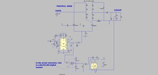
300W, 24VIN, 32VOUT, 225kHz.

The schem attached is the essentials of it (he’s actually used sync rects but I left them off here, for brevity. (He has no snubber or TVS on either sync rects or pri fets.)

What got me the most was his feedback loop……it is as attached….a LT1431 used as an “opamp integrator”……then this drives into a digital isolator (ADum1280)…which goes into the COMP pin of the LTC3723 on the primary side.

LT1431 datasheet.

ADum1280 datasheet
https://www.analog.com/media/en/technical-documentation/data-sheets/ADuM1280_1281_1285_1286.pdf

LTC3723

I’ve told them it’s a defective schem, due to the feedback but they insist he knew what he was doing.
Do you know what he might have been trying to do? Was he on the verge of some superb new technique?

LTspice and essentials of schem attached
 

Attachments

  • Pushpull 300w.jpg
    Pushpull 300w.jpg
    114.8 KB · Views: 103
  • pupull300w_LT1431_ADuM1280.zip
    2.5 KB · Views: 91
Last edited:

not being an expert, and not having spent a lot of time analyzing:
what's wrong with the feedback?
the AD1280 should work okay. i am fascinated by the two itty bitty transformers therein, but it covers the isolation
and its 23 ns propagation delay isn't much different than an optical isolation.

the 1431 is a shunt regulator - like a TL431

i must have missed the 1241 - i don't see it in the schematic

the most odd thing about this is "So they sent it to us to finish off."
you have the prototype - did the engineer turn it on for you? If so, did it work?
 
...my apologies....i meant "LT1431", rather than "LT1241".
I never met the engineer....he told his company that it worked...i never saw it working.

what's wrong with the feedback?
the AD1280 should work okay.
...Thanks, it uses a Digital Isolator. (ADuM1280) ..instead of an opto to send the "feedback signal" back to the primary side.
As you know, this only gives essentially rough ON/OFF control.

isn't much different than an optical isolation.
...though i am sure you appreciate, its a digital isolator.....these cannot be used in a frequency compensated feedback loop design.
___________________--
Not only that, but with the digital isolator connected (effectively what the shown LT1713 comparator is) the way he has it, its the wrong polarity, it would need to be an inverting digital isolator.................i noticed on the PCB, that has has a wire going to the ADuM1280 secondary side Vcc pin (pin 1), because he forgot to put a PCB track to it...........so i actually suspect, that when he had it "working"...the digital isolator was not even powered, and the pull up resistor on the COMP pin was responsible for making it "work." [referring to schem of top post].......Aaaah...just seen in ADuM1280 datasheet that when pin 1 has no power, then the output of the digi isolator is high by default......this i now believe, is how he had it "working". (Also, i now see he had put a 10V supply into the ADuM1280, so he probably killed it.......so it wasnt really even "there"...and the COMP pin pullup resistor is what made it "work".
____________________
In his extremely brief notes, he did 'fess up about his 6.8uH inductor being too low in value.
He also reckoned he's got a turn-on spike problem....and says he increased LEB on the LTC3723-1 which gave a bit of help.
The transformer is Planar and has the shown inductances, and 1.2uH of leakage , measured at 10kHz......i saw that it cost £46 each, for 20 off.
____________________
Ive seen some of his other work...he obviously has potential....i suspect they had him in an environment where it was impossible for him to concentrate or something like that. Like many junior EE's, they are too shy and quiet to speak up when the environment is not conducive to their "concentrated effort."
 
Last edited:

Status
Not open for further replies.

Similar threads

Part and Inventory Search

Welcome to EDABoard.com

Sponsor

Back
Top