mcmsat13
Member level 5
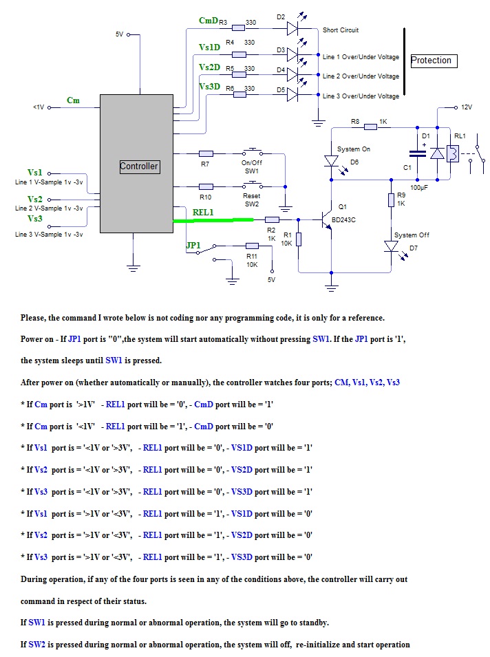
3-Phase Motor Protector
I have done this with discrete and passive components, it works but there are so many parts and thus complexity. I want to know if MCUs can deliver more accurate result.
This picture is only the block diagram of the proposed design. The components here are only for reference. You can choose any component that work best for the purpose.
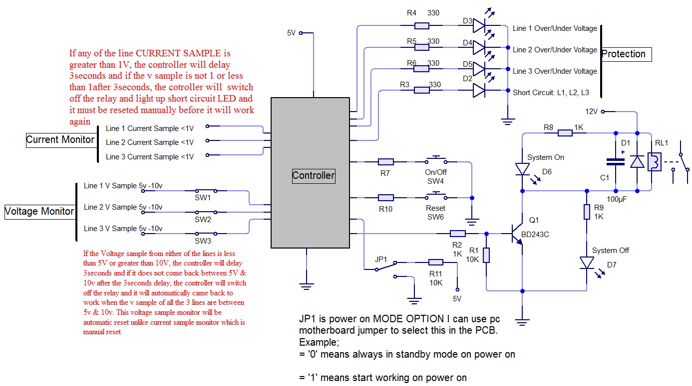
If any of the line CURRENT SAMPLE is greater than 1V, the controller will delay 3seconds and if the v sample is not 1 or less than 1 after 3seconds, the will switch off the relay and light up short circuit LED and it must be reseted manually before it will work again
If the Voltage sample from either of the lines is less than 5V or greater than 10V, the controller will delay 3seconds and if it does not come back between 5V & 10v after the 3seconds delay, the controller will switch off the relay and it will automatically came back to work when the v sample of all the 3 lines are between 5v & 10v. This voltage sample monitor will be automatic reset unlike current sample monitor which is manual reset.
JP1 is power on MODE OPTION I can use pc motherboard jumper to select this in the PCB. Example;
= '0' means always in standby mode on power on
= '1' means start working on power on
The block diagram speaks clearly about this design. If anything is confusing please ask me to clear the area.
Thanks in advance.