cgchas
Member level 3
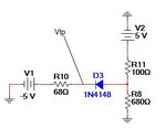
I am trying to analyze this circuit. I can do it without the diode using Thevenin equivalence and the simulator agrees, but with the diode in the circuit, my current calculations are a bit off and my voltage at test point Vtp is off as well.
The simulator shows the following:
current in the branch with the 68 ohm resistor is -55.235mA
current in the branch with the 100 ohm resistor is 54.564mA
current in the branch with the 680 ohm resistor is -671.11uA
voltage as Vtp is -1.244V.
I am using .64V as the forward biased voltage drop for the diode. The part in the simulator is 1n4148.
With my calculations, I am getting:
-53.633mA in the 68R branch
55.3936mA in the 100R branch.
I feel these values may be close, but off enough to consider the possibility that I am analyzing incorrectly.
Attached is a schematic. Any help is appreciated.