Continue to Site

Welcome to EDAboard.com

Welcome to our site! EDAboard.com is an international Electronics Discussion Forum focused on EDA software, circuits, schematics, books, theory, papers, asic, pld, 8051, DSP, Network, RF, Analog Design, PCB, Service Manuals... and a whole lot more! To participate you need to register. Registration is free. Click here to register now.

12v Battery Charger Circuit with Auto Cut off

Status
Not open for further replies.

rst

Newbie level 3
Joined
Sep 4, 2015
Messages
4
Helped
0
Reputation
0
Reaction score
0
Trophy points
1
Activity points
29
i saw this cct in circuit gallery and i have some question about it

1-what will be the voltage on( cv or pin 5)coz it internally connect to voltage divider
2-i think red led always on ..then what is purpose of it ?

**broken link removed**

Working
Positive terminal of the upper comparator of 555 is connected with reference voltage in order to turn OFF the charger if the battery charges above 13.8V.

why they said Positive terminal ?????? i think ( cv or pin 5) is negative terminal
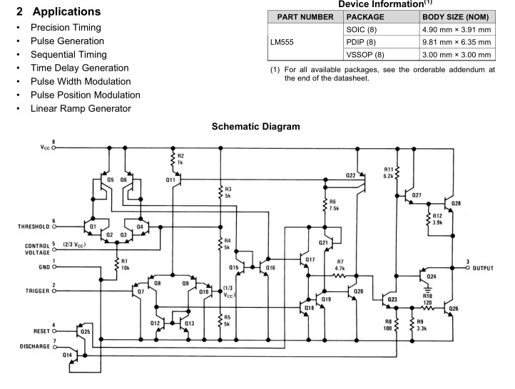
 

Pin 5 CV is a 5.1v reference because of zener diode.
Pin 2 TR is an adjustable sample of the battery voltage for comparison.
Red LED indicates presence of AC power.
Green LED indicates charge mode.
 

Like many circuits from that website, this circuit is WRONG.
The reference voltage for the pin 6 comparator is 5.1V by the zener diode so when the battery voltage is 5.1V or higher then the charger turns off. Stupid!
The pin 2 voltage is the battery voltage divided down by the pot so when the battery voltage becomes lower than the pot divider setting then the charger turns on.

DUH, the red LED lights when the circuit has power from the mains, which is what is said in the text.
 

**broken link removed**
This is a terribly inefficient design for a charger. I do not recommend it, even if it worked. Just imagine. You have a 15Vac, 5A transformer (75VA) that even if you could transfer 2A across the power resistors (ESR.= 5Ω @20W) the V drop would have to be I*R=10V !!!..

A poor match for maximum power transfer or efficiency. Perhaps 2A is about the maximum for a battery drained to 10V with 21Vp from the bridge and 3 diode drops. 20W is pretty poor from a 75VA transformer.

There is a lot of misunderstanding around the 555, perhaps due to poor documentation of this application and internal workings by the chip OEM.
So to make it easy to use, the OEM show typical applications, with a simple block diagram, with total disregard to logic. After all it is analog chip, but are the SET/RESET functions active low or high? (low) Does that affect the comparator polarities? (yes) Do they tell you this? (no) Did you assume positive logic or negative logic for external? What happens when both R and S of internal FF are active? i.e. which dominates Q? TR=Trigger=internal Reset)

In this case external Reset! is inactive high.

To fully understand it, learning to read schematics simply by using logic and following inputs to outputs. I say to myself, normal or + in and then invert the "word" after each collector out and keep the same for each emitter out until you reach the output. If it is inverted, I say it is negative logic or -ve analog input.

Although I have never used a 555 in my life, for reasons like, it's a solution for those who don't really understand electronics, I'd rather make my own. it is actually a very flexible analog/logic chip if you can really understand it's internal workings.


SO the way I would explain it is, the output is driven by an SR Flipflop with SET driven when "Trigger>Control" or TR>CV where TR is a pot adjust so that when Vbat reaches 14.3, scaled by Pot to get TR>Zener~5.1V. Since SET is high and that activates Relay coil, the contacts are backwards and shown be shown in the power off state as NC meaning Q out=1 turns off charger and drains battery from coil current. :( Otherwise reverse TH and TR and add scaling R's to make it shutoff and Turn ON with hysteresis.

DO NOT FOLLOW THIS DESIGN.. IT IS FAULTY, but can be made to work.

The charger must shut off permanently or else the relay will oscillate without a battery and hysteresis.
( bad design)

Actually Relay should turn off when battery is undercharged and the VOut can drive a relay easily, so no transistor needed.

9140275200_1444576830.jpg

TH = Threshold with negative logic and Vcnt either being 2/3Vcc if floating or equal to external control, in this case Zener 5.6V which is compared with TH=Threshold input and TR=Trigger is now compared with CV/2=Control Voltage with internal 5k/5k divider.

As shown RESET is active with AC power with RED LED.

SET is active when VBat/2 exceeds Zener reference.
SET drives the coil, and turns on GREEN LED, which therefore must disconnect the charger.

If AC is OFF, then the Charger RESET's should open the contacts to the battery or when it is fully charged. Thus a window comparator using two opamps is suitable such as found in the 555. A reference V is needed such as a zener, although not as precise as a bandgap diode. The Relay contacts will wear out quickly with discharge from a 3,300 uF Cap to a 100F Battery, so this should not be so big and doesn't need to be.

The specs are not given nor is the design efficient or effective, but in practice can be made far better with a hysteretic buck converter using the PWM config of the 555 with a storage inductor.

Always start a good design with specs and functional description.

Honestly the Website developers "i-St@r Group" who branded this design, were rookies.
 

TO start a good design start with logical functional design spec;
e.g.

  • Since internal RESET in 555 overrides internal SET, make the charge function ON with RESET=on or active low Vout.
  • internal Reset is controlled in 555 by TH>CNT(=5.1 here) controlled by pot for cutoff on TH set to 14.3V tapped to = CNT (5.1V here) thus charger shutoff or RESET occurs when Lead acid reaches 14.3V
  • Internal SET can be anything < RESET which is when TR<CNT(=5.1V here) . I would suggest when charger is off Vbat@100%=12.5V so choose TR =5.1 when Vbat=12.4V, then choose R ratio to match or use a pot. THis gives slow hysteresis between charge , float and discharge of battery below 100% SOC.
  • For PWM control with inductor instead of 5 Ohm ( 1 Ohm better) series limiter, use FET instead of Relay an 100uH 5A choke to make an efficient hysteretic BUCK switching regulator.
  • Disable charger if external power is not present.
  • Enable RED LED is external Power is present
  • Enable GREEN LED is Charger is active (Vout=low)
  • Keep in mind Bridge rectifier has a root two peak multiplier above rated load VA output voltage with no load ( plus secondary loss drop of 10% typ. or ~1.5x rated RMS voltage out for no load.
  • Also bridge diode output current does not need 1500uF to power regulator It just needs 5RC= 1/2f (=1/100Hz or 1/120Hz) where R is the regulator power equivalant load and C ends up being around 10~100uF to drive LEDS and 555 and output load. Remember a battery is equivalent to almost 100F~10000F where C=I*dt/dV, so for a strong car battery of 40Ah capacity with a drop of 1V from 12.5 to 11.5 ,
  • C~40A*1h/1V=40*3600s=144,000Farads !!
  • Car Battery ESR for a 700CCA rating of (12.5V-7.5V)/700A= ~7mΩ, since CCA rating is for battery current with 30 second hold at 7.5V volts
  • If using a power switch or MOSFET to drive battery, choose one much lower RdsOn than transformer winding resistant and diode ESR for cool operation. Power transformer for this small size is around 95% efficient. ( big ones are up to 99.5 (MVA)

Now you can start a design.

- - - Updated - - -

For another simpler spec;
  • If Charger input V> Vbat enable Charger and turn on RED LED
  • If Vbat >14.3V disable charger and over-ride above anbd turn ON GREEN LED to indicate Full Charge.
  • otherwise enable suitable state of Vout to switch charger to battery and turn on GREEN LED.
  • Decide if you need AUTO CUT-OFF charger when done or Continuous regulation for Trigger to turn off charger and maintain 14.3V ( or 14.2V)

To design this all you need is a reference voltage, a "window comparator" or just a comparator with x% Hysteresis and a low resistance Switch ( Q or Relay) ( and diodes) that can handle 100A surges. due to low battery ESR 1Vdrop/0.01Ohm
 
Last edited:

Status
Not open for further replies.

Part and Inventory Search

Welcome to EDABoard.com

Sponsor

Back
Top