Continue to Site

Welcome to EDAboard.com

Welcome to our site! EDAboard.com is an international Electronics Discussion Forum focused on EDA software, circuits, schematics, books, theory, papers, asic, pld, 8051, DSP, Network, RF, Analog Design, PCB, Service Manuals... and a whole lot more! To participate you need to register. Registration is free. Click here to register now.

10MEG resistor to set switching frequency of Buck?

cupoftea

Advanced Member level 5
Joined
Jun 13, 2021
Messages
2,611
Helped
54
Reputation
108
Reaction score
115
Trophy points
63
Activity points
13,685
Hi,
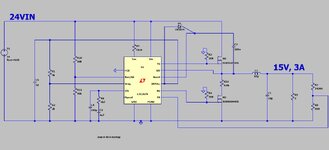
We are doing a 214kHz Buck with 24vin and 15vout at 3a(out).(as attached in LTspice)
Using the LTC3878.
-Though it needs a 10 Meg resistor into its RON pin in order to give the 214kHz.
That means a current of just 2.3uA into the RON pin of the LTC3878.
Surely using a 10 MEG resistor to set the switching frequency is asking for trouble? (with noise)

LTC3878 datasheet
 

Attachments

  • LTC3878 BUCK.jpg
    LTC3878 BUCK.jpg
    168 KB · Views: 40
  • LTC3878 BUCK.zip
    1.3 KB · Views: 45
Hi,

I don´t see a problem in detecting 2.3uA. To keep noise low, just make the node as small as possible.
--> place R9 close to the IC pin.

In the datasheet there is a chart "On-Time vs I_ON Current" ... which shows I_ON go down to 1uA


Klaus
 
I see you haven't mastered how to simulate parasitics.

My advice was a result of verifying my advice in LTspice. The consequences increase 50 mVpp output ripple on Vout-15 or worse , overshoot, freq. and damping factors by changing loop gains from +ve or -ve x pF feedback to Ion from each nearby signal.

If you can imagine it, you can simulate it.
Tony
 
Last edited:

LaTeX Commands Quick-Menu:

Part and Inventory Search

Welcome to EDABoard.com

Sponsor

Back
Top