Continue to Site

Welcome to EDAboard.com

Welcome to our site! EDAboard.com is an international Electronics Discussion Forum focused on EDA software, circuits, schematics, books, theory, papers, asic, pld, 8051, DSP, Network, RF, Analog Design, PCB, Service Manuals... and a whole lot more! To participate you need to register. Registration is free. Click here to register now.

Scoping output ripple voltage of a 3MHz SMPS using probe PCB adapter

Status
Not open for further replies.
T

treez

Guest
Hello,
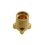
We are scoping the output voltage of a 100W (1V5, 65A output) , 3MHz Vicor VTM48’ power module with a Scope Probe PCB Adapter (as in attached JPEG) soldered into the PCB. This is essential since the 3MHz VTM48 module cannot be scoped with the scope probe with its ground 'tail' clip, -because there’s too much noise like that.

However, even when using this probe PCB adapter, the result is inaccurate, and there is more ripple shown on the scope than actually exists…..a good percentage of the ripple is coupling into the scope probe lead. –We know this because when you touch the scope tip to some ground net copper, and also connect the scope GND barrel to the same GND net via a little bit of stiff wire, you can then see all the “Pickup”. The “pickup” has an amplitude about half that of the ripple amplitude seen when the output voltage is scoped with the scope probe PCB adapter.
Therefore, half of the ripple seen when scoping the output is just “pickup”.
As you know, its important to assess the degree of ‘pickup’ by probing with the scope tip and barrel both connected to the same GND net. As such, why is it not common to see the Scope Probe PCB adapters soldered into PCB’s such that the entire adapter metal is connected to the same GND net….then its easy for people to just shove the scope probe into the adapter and look at the amount of “pickup”.

So why is this rarely done?
 

Attachments

  • Scope probe PCB adapter.jpg
    Scope probe PCB adapter.jpg
    5 KB · Views: 145

I'd guess because although it tells you roughly how bad
your measurement quality is, the data obtained isn't really
good for anything?

Wonder whether you might be better off with a 50-ohm
system, it would be a trivial incremental load and might
be much less susceptible to local EMI than the 1Mohm
scope probe and its innards.
 
  • Like
Reactions: treez

    T

    Points: 2
    Helpful Answer Positive Rating
Here are some helpful ideas for ripple measurement

http://www.eetimes.com/document.asp?doc_id=1273282

limit the bandwidth of the scope.

wrapping the scope lead around a ferrite core can help minimize common mode currents.


http://e2e.ti.com/support/power_man...-measuring-and-reducing-output-voltage-ripple

The ripple measurement should be DIRECTLY across the output capacitor.

50 ohm measurement technique.

calculating parasitic capacitance.


AN-1144 Analog Devices PDF

50 ohm measurement the best.

Can use RG174 type cable.
 

Attachments

  • AN-1144.pdf
    3.3 MB · Views: 114
  • Like
Reactions: treez

    T

    Points: 2
    Helpful Answer Positive Rating
Wonder whether you might be better off with a 50-ohm
system,
..This thread discusses the comparison of using a scope probe and a piece of coaxial cable for smps output ripple voltage measurement.

- - - Updated - - -

I'd guess because although it tells you roughly how bad
your measurement quality is, the data obtained isn't really
good for anything?
Thanks but its really useful, it shows how much of the waveform is just pickup.....i mean, yes, the best case is to have no pickup in the measurement, but thats difficult without going to great expense for a 3MHz SMPS
 

Sorry here is the thread,
https://www.edaboard.com/threads/358562/
but it does seem that coaxial cable with series blocking cap is best, as well as scope with a 50ohm termination.
I dont think a 50 ohm resistor is needed at the measurement side (PCB end) of the coaxial cable...but one place where i worked use to do that.
 

I suspect that much of the noise being seen is common mode current in the cable screen, try winding a dozen turns of the cope lead thru a FT43 torroid or such.

TBH, by 3MHz at those sorts of amplitudes, I would be looking at doing a 50 ohm system (Still with common mode suppression), there is a reason all the RF cats do matched impedance. For your purposes a 50 ohm coax, with 50 ohm termination at the scope, a 100nF coupling cap and some ferrite on the cable as a balun is quick and easy.

Regards, Dan.
 
  • Like
Reactions: treez

    T

    Points: 2
    Helpful Answer Positive Rating
Thanks, Do you know what are the part numbers or names for the connectors of the attached test rig?
It is taken from the link kindly supplied by FlapJack above. Also, how have they managed to solder the grounded outer of those BNC plugs to the PCB?

FlapJack’s link
http://e2e.ti.com/support/power_man...-measuring-and-reducing-output-voltage-ripple

It looks like an SMA connector, two BNC male connectors, and an SMA to BNC adapter. Also, its years since ive connected an SMA to a piece of coax, do you know the part number of a cheap tool to do it with?
 

Attachments

  • Vout ripple test lead.jpg
    Vout ripple test lead.jpg
    52.8 KB · Views: 137

Not bad to have 50 ohm parallel termination, but it doesn't bring actual advantage for the frequency range of interest. 50 ohm source side series termination might be suggested if the signal frequency range exceeds 50 MHz to avoid cable reflections.

The common mode choke cores suggested by FlapJack and Dan Mills are however essential.
 

Except that 3Mhz fundamental may have meaningful energy up where it matters.

Personally I would just buy a DC block already fitted with appropriate connectors on fleabay, it should only cost a tenner and (If you get a little selective about manufacturers) will be good for way more then you need.

Regards, Dan.
 

Do as per FlapJack. We measure noise with 50 ohms system.
Oscilloscope : 50 Ohms input, DC coupled, Offset adjusted. lower voltage/division capacity like 2mV or 3mV/div, try with 20 Mhz BW limit for better performance.,
Cable : RG174 cable(rf174-04sp3-04sp3-2000 these cables are avbl fom samtec) has very small core, useful in soldering directly across output capacitor. Their performance is also good.
Directly solder across output capacitor RG174 coaxial cble one end, other end connected to any DSO
 

Looks like Dan Mills has the correct keyword. I searched for "BNC DC block" on google images and eBay and it comes right up. Every electronic distributor in the USA showed up but not Farnel.

Treez, no reason to fool around making cables. Buy a BNC with RG174 cable and cut it in half and you have a spare to connect to the capacitor (keep lead short to capacitor from BNC, best guess 6" to 1 foot. RG174 has more loss than regular 50 ohm cable).

Keyword "BNC to RG174 cable" comes right up on google images and eBay.
 

Thanks for suggesting the DC Block component and 50 ohms system.....

We just did a Vout ripple measurement but instead of the capacitor shown for DC blocking purposes in the above “Vout ripple test lead”, (of post #7)we used a DC Blocker component by Mini Circuits Ltd (Part number BLK-89-S+).
The results are striking, and there is about five times less pkpk ripple seen on the scope than when using the barrel/tip of a normal x10 scope probe.

The results were so good, that I am wondering if we must have missed something, and its our use of the DC blocker component that’s attenuating the ripple? I beg your advice.

DC Blocker Datasheet(Part number BLK-89-S+)
https://www.mcl-yokohama.co.jp/webdata/BLK-89.pdf

The BLK-89-S+ DC Blocker has a dB loss of 0.02 at 3MHz, (our switching frequency), and so since 20.log(Vout/Vin) = 0.02, that means that Vout and Vin are pretty equal. You agree.
 

0.02dB is an utter irrelevance.

Do make sure you are terminating into 50 ohms at the scope, and do use a ferrite common mode choke.

Obviously, if you also source terminate then you will be seeing the action 6dB below reality if you don't compensate for it, but I am not sure I would bother with source termination for this.

Nothing wrong with that DC block, Minicircuits make very good RF toys (I have a case full of that stuff, Attenuators/Filters/transformers it is all excellent).

It does however never hurt to test your test gear, hook up a known source and measure it, a lab signal genny should do, but remember that it may or may not specify output level into a terminated load).

Regards, Dan.
 

Directly solder across output capacitor RG174 coaxial cble one end, other end connected to any DSO
Thanks, so you dont use a DC blocker?

- - - Updated - - -

The common mode choke cores suggested by FlapJack and Dan Mills are however essential.
Thanks, we used a cable ferrite round the scope lead and it made no difference though
 

I must admit in the end the x10 probe with "spring" connector was just as good as the 50 ohm coax system with DC blocker ...the problem with the "spring" method is that its so awkward to hold it steadily on right on the capacitor terminals......whereas the 50 ohm coax can be directly soldered to the capacitor terminals...which as you know, is where the probe must be for such ripple measurements.
 

Status
Not open for further replies.

Similar threads

Part and Inventory Search

Welcome to EDABoard.com

Sponsor

Back
Top