Continue to Site

Welcome to EDAboard.com

Welcome to our site! EDAboard.com is an international Electronics Discussion Forum focused on EDA software, circuits, schematics, books, theory, papers, asic, pld, 8051, DSP, Network, RF, Analog Design, PCB, Service Manuals... and a whole lot more! To participate you need to register. Registration is free. Click here to register now.

Voltage Divider Input for Dual Polarity Output SMPS

Learner1234

Newbie level 6
Joined
Jan 20, 2024
Messages
12
Helped
0
Reputation
0
Reaction score
0
Trophy points
1
Location
Australia
Activity points
98
Hi guys. I have to design a dual polarity output SMPS. I'm quite puzzled how to implement the input voltage divider section for that.

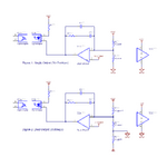
As an example plz see the attachment. The figure 1 is ok as it is single supply output section and no problem with input voltage divider resistors.

However for dual polarity output power supply section given in figure 2 is not complete and I have simulated in LTspice and it shows that R Upper- (R9) resistor in figure 2 has no impact on the loop, being grounded and only R Upper+ (R7) and R Lower+ (R8) will define the output voltage, hence if load at both outputs are balanced always then no problem and if not balanced then it's in problem. Also there will never be any check on negative supply rail for regulation. I have searched the net and could not found any method which caters this issue if OpAmp is used and particularly if single OpAmp is used with another restriction that it should be single supply OpAmp. In case of TL431 there is easy method to implement dual polarity output but I'm bound to use one single supply OpAmp only, or any corrections needed in figure 2 so that this sections becomes complete in itself. Any idea how to implement it.
 

Attachments

  • Control Loop Input for Dual Output.png
    Control Loop Input for Dual Output.png
    46.5 KB · Views: 60
Hi,

Schematic:
Mind: Signal flow in a schematic should be left to right.

--> Please confirm: You want two outptus, one positive, the other negative. Both the same magnitude in volts.
--> fixed output voltage or adjustable output voltage?
--> what is your power stage (output) topology?
--> what (which value) exactly do you want to regualte?

Klaus
Got it for sch flow


Yes one positive & other negative & same in magnitude.

It's fixed output voltage.

It's full bridge center tapped rectification.

It's +-80V output.
 
Last edited:
You can actually do an LLC , with split secondary, and make the "positive going oscillation go into the + coil, and the negative swing go into the neg coil...with some diodes. (ie every switching period, each half supply gets a pulse of current)
The just regulate the one coil. And have a safety trip comparator on the non reg'd coil.
Well, youll need current limit anyway, so you could put bipolar current limit on the pri, say.
 
Are the dual outputs are regulated by a common input or individual?
Your schematics look identical and have no effect from -20 with the inserted gnd.
I already said that I'm not clear how to regulate both polarity rails using one single supply opamp. The main issue is how to consider input of voltage divider connected to output side for feedback.
--- Updated ---

You can actually do an LLC , with split secondary, and make the "positive going oscillation go into the + coil, and the negative swing go into the neg coil...with some diodes. (ie every switching period, each half supply gets a pulse of current)
The just regulate the one coil. And have a safety trip comparator on the non reg'd coil.
Well, youll need current limit anyway, so you could put bipolar current limit on the pri, say.
I have to regulate both rails using one single supply opamp.
--- Updated ---

Note: Although I can't use TL431 independently, I have the option to pass sense voltage divider resistors output to reference pin of TL431 instead of opamp inverting input but optocoupler driving circuitry must be around one single supply opamp referenced to ground. Now I think it looks easy....
 
Last edited:
The main issue is how to consider input of voltage divider connected to output side for feedback.
The basic question is about power stage topology which wasn't yet mentioned at all. There are different concepts for multi output SMPS, etc. used in PC power supplies.
 
You have not defined your design specs, load regulation error or imbalance issue yet other than it’s a tracking problem yet to be designed.

start with load specs then tolerances and show enough details so we can see the problem.
 
Hi,

I asked about topology
I asked about "what" you want to regulate.

Topology:
Let´s say you have a flyback topology, using a single transformer with one primary coil and two secondary coils (for the two outputs).
Then it´s simply impossible to regulate each output voltage independently.
The keyword is "independently". Because there is only one transformer ... the depend on each other.

An example for this (impossible) case:
You want one output to be +20V, but actually it is +18V ... thus you need to INcrease primary current pulses.
While at the same time the other output is expected to be -20V, but it actually is -22V .... thus you need to DEcrease primary current pulses.

"What" to regulate:
In the example above ... how do you want the regulation loop to operate:
1) it could say it regulates on output 1 only (many power supplies operate this way. They regulate on the most critical channel only)
2) it could regulate on output 2 only
3) it could regulate that each output has "at least" the expectd (+/-) 20V .. in this case it increases regulation for the positive side to get 20V ... and accepts that the negative side gets even higher (neg)
4) it could regulate that each output has "maximum" the exepected 20V .. in this case it decreases regulation for the negative side to get -20V ... and accepts that the positive side gets even lower
5) or that the total voltag eacros both outputs is 40V....
6) or whatever you want


Klaus
 
Hi guys thanks for you explaining the requirements, particularly @KlausST
Luckily I have resolved the issue & don't see the need to disclose further & if any questions remain, I will be back.
 
Luckily I have resolved the issue & don't see the need to disclose further & if any questions remain, I will be back.
The idea of a forum is that other peoply gain information by reading the threads.

Thus - if you have a solution - or other beneficail informations ... you are expected to post it here.


Klaus
 
In AT PSU's the forward converter is tightly coupled to each secondary such that ( I believe most if not all) only the 5V need feedback to be regulated and the other voltages track with only a small cross-regulation error.

In future please try to disclose enough information to analyze the problem.
 

LaTeX Commands Quick-Menu:

Similar threads

Part and Inventory Search

Welcome to EDABoard.com

Sponsor

Back
Top