Continue to Site

Welcome to EDAboard.com

Welcome to our site! EDAboard.com is an international Electronics Discussion Forum focused on EDA software, circuits, schematics, books, theory, papers, asic, pld, 8051, DSP, Network, RF, Analog Design, PCB, Service Manuals... and a whole lot more! To participate you need to register. Registration is free. Click here to register now.

[SOLVED] True Sinewave Inverter - Output LC filter design help needed

Status
Not open for further replies.

baileychic

Advanced Member level 3
Joined
Aug 2, 2017
Messages
728
Helped
56
Reputation
112
Reaction score
57
Trophy points
28
Activity points
7,033
True Sinewave Inverter - Output LC filter design help needed

Hi,

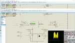
I have designed a true sinewave inverter for single phase 220V 50Hz. I am using 12V Battery voltage to 325V DC VBUS voltage DC-DC Converter (not shown in simulation). My SPWM is ok. The issue is I am not getting sinewave signal at the output. Please tell me how to design a good LC output filter.

I used the formula f = 1 / (2Pisqrt(LC))

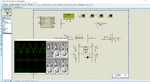
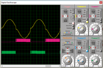
My SPWM frequency is 16 KHz and so I chose cutoff frequency for filter as 3 KHz. I need 50 Hz fundamental sinewave output. SPWM is ok because if I connect RC low pass filter then I get pure sinewave output. I am attaching my Proteus simulation file. I am also testing on hardware. In both I am getting this distorted signal.

L = 1/(4 * 3.14159265^2 * 3000^2 * 2.2uF)

L = 1.279mH

- - - Updated - - -

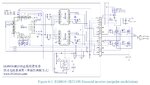
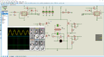
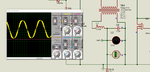
I am actually making two versions of the Inverter. One is based on DC-DC Converter with switching transformer to get 325V DC VBUS voltage for H-Bridge from 12V Battery voltage. Another is I am using 12V to 220V step-up output iron core transformer at the H-Bridge output. Now, I changed the inductor and capacitor values and I am getting this signal at the output. It is still not pure sinewave. I know the distortion at ZC is due to Mosfet. How can I eleiminate it to get pure sinewave ? I am using IRF840. See attached image.
 

Attachments

  • True Sinewave Inverter.png
    True Sinewave Inverter.png
    236 KB · Views: 761
  • True Sinwave Inverter.rar
    44.4 KB · Views: 245
  • Pure Sinewave Inverter.png
    Pure Sinewave Inverter.png
    191.9 KB · Views: 551
Hi,

I have made a pure sine wave 3 phase power inverter but its been some time. I dont have the exact values with me right now but I'm sure if you use following formulas you will get good results. Try it in proteus first.

LC-Filter-calculation1.jpg


If you need more power than make sure you get high ampere rating inductors.
Good Luck!
 

You want to start filtering out frequencies above 80 or 90 Hz.
If L value is too high it reduces amplitude to your load. Select C so it assists filtering action above 80 or 90 Hz.

You'll find you must adjust L:C ratio to suit the load. The greater the Ampere load, the less the LC ratio.
 

@BradTheRad

I choose cut of frequency as 1800 Hz and C as 2.2uF

So,

L = 1/((2*3.14159265*1800)^2*2.2*10^(-6))

= 3.55mH

and finally I chose standard values of 3.3mH 6A and 2.2uF but still I am not getting pure sinewave.

Also in the transformer based Inverter why I am getting crossover distortion ?
 

I choose cut of frequency as 1800 Hz...

Why so high value for the cut-off? For 50Hz operation, please choose the cut-off below 100Hz. You should get a decent sine wave output (it is not going to be 100% pure)
 
If I choose L as 3.3mH and fc as 90 Hz then C value increases greatly. If C value is greater than 4.7uF then I have to use two electrolytic capacitors connected back to back. I can't get more than 4.7uF Non-Polarized Capacitors.

Is 10mH and 330uF values ok ? I chose cutoff frequency as 90 Hz.

- - - Updated - - -

I am doing calculation like this. I can't increase L much because amplitude of the output will decrease. If I keep L small then C increases and I can't get C in Non-Polarized Capacitor type. What is the work around ?

P = VI

I = P/V = 500W/220V = 2.27A

Ipk = 2.27*1.4142A = 3.214A

Characteristic Impedance of Inverter = 220/2.27 = 96.916 = approx 97 Ohms

X = 2*pi*f*L

1% of 97 Ohms = 0.97

Zo = 0.97 Ohms

L = Zo / (pi x Fc) Henries


C = 1 / (Zo x pi x Fc) Farads


Fc = 1 / (pi x square root ( L x C) Hz

L = 0.97/(3.14159265*90) = 3.4mH

C = 1/(0.97*3.14159265*90) = 3646uF


I think the above equation which I took from here are wrong.

https://www.radio-electronics.com/i...f-filters/simple-lc-lowpass-filter-design.php

I fixed the equations.

L = Zo / (2 x pi x Fc) Henries


C = 1 / (Zo x 2 x pi x Fc) Farads


Fc = 1 / (pi x square root ( L x C) Hz

Still getting 1.7mH and 1823uF for fc = 90Hz.
 
Last edited:

I referred this.

https://electronics.stackexchange.com/questions/98300/50-60hz-inverter-output-inductor-design

It says, fc can be 1/10 of switching frequency and also it tells fc = SQRT(fo * fpwm)

So, in my case it is fc = SQRT(50 * 16000) = 894 Hz.

I choose approx double of it.

My switching frequency is 16 KHz and so, I can choose fc = 1.6KHz

I choose C = 2.2uF 630V as it is easily available and L as 3.3mH 6A type.

So,

fc = 1/(2*3.14159265*sqrt(3.3*2.2*10^(-9))) = 1867 Hz which is close to 1.6 KHz.

Also, i referred the attached circuit of commercial EG8010 based Inverter and its switching frequency is around 24 KHz and they are also using 3.3mH and 2.2uF for the output filter. So, I decided to use same values as I have also calculated same values.

See the Proteus Simulation screenshot. For transformer based Inverter now there is no crossover distortion but still there is a little PWM component in the sinewave.

For DC-DC converter based Inverter the same filter is not working even though it works fine in EG8010 circuit.
 

Attachments

  • SPWM Unipolar Modulation.JPG
    SPWM Unipolar Modulation.JPG
    226.7 KB · Views: 399
  • PSWIOTBSOK.png
    PSWIOTBSOK.png
    184.7 KB · Views: 438
Last edited:
This is my simple simulation. The load gets 220 VAC, 2A, 50Hz sine shape.
Carrier 5 kHz.

op amps SPWM LC 2nd-order load gets 220 VAC 2A.png

The inductor is a value which has little impedance to 50 Hz. Your method of calculating yields a result of a few mH which is satisfactory at your carrier frequency.

It is not readily obvious how to calculate the capacitor value. From watching simulations it appears that the capacitor generally carries about the same level of current as the load (although not necessarily in sync). So in addition to filtering, its purpose is also to do some amount of power factor correcting. Therefore it can be calculated to have an equal impedance as the load at 50 Hz. It does not need to be so great as 330 uF.

- - - Updated - - -

A 4uF value might be okay to use after all, assuming your load is 2A or less.
 
But what about the inductance of the transformer secondary and also about inductive loads like ceiling fans ? Will the output will be still good ?

You have choosen resistive load of 110 Ohms.

For 100W bulb resistance is

P = VI

I = P/V = 100/220 = 0.4545A

R = V/I = 220/0.4545 = 484 Ohms.

Can you show output signal for this load ?
 

But what about the inductance of the transformer secondary and also about inductive loads like ceiling fans ? Will the output will be still good ?

The nature of an inductor is that it continues to pull current after current is shut off. (Similar to power factor error.) The H-bridge has devices which turn Off and On. Therefore because of the LC filter you must also put more effort into designing things so components act compatibly. It might be okay if you use mosfets thanks to the body diode. This provides a loop for current to travel around.

However motors and inductive loads tend to increase the overall Henry value. There are several possible arrangements for a filter. The aim must be to maximize power factor, to avoid having inductors try to draw overmuch current during H-bridge Off times.

R = V/I = 220/0.4545 = 484 Ohms.

Can you show output signal for this load ?

Slightly different arrangement. Carrier = 1500 Hz.
Values were adjusted while observing the scope traces, until behavior seems to 'look feasible'.

op amps SPWM LC 2nd-order load gets 220 VAC 0_4A.png
 
My previous question got solved. I have a new question and as it is related to same project I am asking it here only. I was earlier using Thamid's code but I was not getting pure sine wave and so I changed the sine table and the ISR code but I see a little distortion. Can somebody tell me where is the bug in my code ?

I was using this code.

https://tahmidmc.blogspot.in/2013/02/demystifying-use-of-table-pointer-in.html

Now, I changed my code like this. I am getting 50 Hz but the signal is slightly distorted.

Code:
const unsigned int sine_table[32] = {
     0,96,191,284,375,461,544,621,692,757,814,864,905,937,961,975,979,975,961,937,905,864,814,757,692,621,544,461,375,284,191,96
};

typedef struct {
  char index;
  char counter;
}INVERTER_TYPE;

INVERTER_TYPE inverter;

//Timer2
//Prescaler 1:1; Postscaler 1:1; TMR2 Preload = 249; Actual Interrupt Time : 62.5 us
void InitTimer2() {
    T2CON = 0x04;
    TMR2IE_bit = 1;
    PR2	= 249;
    INTCON = 0xC0;
}

void interrupt(){
    if((TMR2IE_bit) && (TMR2IF_bit)) {
        //Enter your code here
        
        if(++inverter.counter >= 5) {
            CCPR1L = (sine_table[inverter.index] & 0x3FC) >> 2;
            CCP1CON.DC1B0 = (sine_table[inverter.index] & 0x01);
            CCP1CON.DC1B1 = (sine_table[inverter.index] & 0x02) >> 1;
            
            if(++inverter.index >= 32) {
               inverter.index = 0;
               CCP1CON.P1M1 = ~CCP1CON.P1M1;
            }
            
            inverter.counter = 0;
        }
        
        TMR2IF_bit = 0;
    }
}


void main() {
    asm clrwdt
    
    CM1CON0 = 0x00;
    CM2CON0 = 0x00;

    SLRCON = 0x00;

    ANSELA = 0x07;
    ANSELB = 0x00;
    ANSELC = 0x00;
    ANSELD = 0x00;
    ANSELE = 0x00;

    ADCON1 = 0x80;
    ADCON2 = 0b10110101;

    TRISA = 0x07;
    TRISB = 0x00;
    TRISC = 0x00;
    TRISD = 0x00;
    TRISE = 0x00;

    PORTA = 0x00;
    PORTB = 0x00;
    PORTC = 0x00;
    PORTD = 0x00;
    PORTE = 0x00;

    LATA = 0x00;
    LATB = 0x00;
    LATC = 0x00;
    LATD = 0x00;
    LATE = 0x00;

    Delay_ms(100);

    TRISC = 0x3F;
    CCP1CON = 0x4C;
    inverter.index = 1;
    inverter.counter = 0;
    CCP1CON.DC1B0 = 0;
    CCP1CON.DC1B1 = 0;
    CCPR1L = 0;
    TRISC = 0;
    InitTimer2();
    asm clrwdt
    
    while(1) {

          asm clrwdt
    }
}

I am getting signal like attached image.
 

Attachments

  • PSWI1.png
    PSWI1.png
    82.5 KB · Views: 300
  • True Sinewave Inverter.rar
    48.1 KB · Views: 144

My previous question got solved....

If you also post the solution and how did you get it, we all can be a little wiser and all can benefit.

It may also be better if you post a new problem under a new listing.
 

I chose 3.3mH and 2.2uF as they are used in many Inverters as standard value.
 

What is the transformer (12V to 220V step up Inverter transformer) primary and secondary inductances ?

I am calculating like this.

Vp/Vs = n = SQRT(Lp/Ls)

12/220 = SQRT(Lp/1)

3 mH = Lp

For 12V input to transformer in simulation I am not getting 220V across the output filter capacitor. I am getting 4.7V.

Please tell me how to fix the transformer model.
 

Attachments

  • Pure_Sine_Wave_Inverter.rar
    58 KB · Views: 164
  • PSWI7.png
    PSWI7.png
    116.6 KB · Views: 357
Status
Not open for further replies.

Similar threads

Part and Inventory Search

Welcome to EDABoard.com

Sponsor

Back
Top