Continue to Site

Welcome to EDAboard.com

Welcome to our site! EDAboard.com is an international Electronics Discussion Forum focused on EDA software, circuits, schematics, books, theory, papers, asic, pld, 8051, DSP, Network, RF, Analog Design, PCB, Service Manuals... and a whole lot more! To participate you need to register. Registration is free. Click here to register now.

Design capturing range 350Hz-550Hz by using Hef4046b PLL

Status
Not open for further replies.

Wicky21

Newbie level 6
Joined
Jul 7, 2017
Messages
13
Helped
0
Reputation
0
Reaction score
0
Trophy points
1
Activity points
125
I'm currently doing a project by using the HEF4046B pll. i'm new to this chip

My requirement is to lock the PLL around 350Hz-550Hz. Simply my capturing range should be between 350Hz-550Hz. Since i'm new to this pll somebody help me to select R2,R1 and C1 values. Also to design low pass filter.
I'm using a Adafruit AGC Electret Microphone Amplifier - MAX9814 to pick signals.

below links shows out the datasheet of the pll

https://assets.nexperia.com/documents/data-sheet/HEF4046B.pdf

I gone through with the data sheet and selected values. somebody please tell me whether selected values are correct.
Vdd = 5V
Fmin = 350Hz , Fmax = 550Hz
C1 = 30nF
R2 = 100Kohm
R1 = 200Kohm

I thought to use phase comparator 2. I'm bit confusing how to select low pass filter values(R3, C2). And what is the purpose of Rsf resistor?
 

Hi,

Somewhere you need a clock divider for the PLL clock. What's it's value? Let's call it "M".

This determins VCO frequency range:
* minimum: 350Hz x M
* maximum: 550Hz x M

Then choose a resistor network in a way that the PD output voltage range generates this VCO frequency range...plus some headroom.

Klaus
 
Google for 4046 application notes or tutorials, find e.g. https://www.ti.com/lit/an/scha003b/scha003b.pdf

Rfs is the load resistance of the source follower buffer output, only required if you need a buffered VCO control voltage, e.g. for frequency measurement purposes.

Did you notice that the 4046 signal input is for digital signals? A tone decoder for analog signals, e.g. microphone amplifier output would use an analog phase detector like e.g. NE567 tone decoder does.
 
I haven't notice that. Are you sure 4046 is not a Analog PLL??? Because i thought by using microphone this can be lock. Now im bit confused
 

It's digital. If analog output voltages are needed, they are filtered from the comparator outputs.
If you want to track a microphone signal it is probably still possible but you would have to amplify it to digital levels and clip it. Please explain the purpose of the project, are you trying to measure frequency or use the PLL to track an oscillator to the the input frequency? 350Hz to 550HZ seems an unusual range to deal with.

Brian.
 

Processing the microphone signal with a comparator can work if the signal of interest is considerably stronger than accompanying noise. Otherwise a band pass may be required.
 
It's digital. If analog output voltages are needed, they are filtered from the comparator outputs.

Usually 4046 has got a signal input amplifier (pin 14) so one don't have to worry about proper signal shape/level. But COMP_IN signal (pin 3) should be TTL-like.

From the datasheet:

input voltage sensitivity : typ. 150 mV at Vdd=5V
 
Although Phase comparator II is superior in its capture range (as shown in Table 7 in the datasheet), it is also much more sensitive to noise. You may want to use Phase Comparator I in your application.
However, the previous poster's suggestions still apply: amplify and band-pass filter your signal.
 

It's digital. If analog output voltages are needed, they are filtered from the comparator outputs.
If you want to track a microphone signal it is probably still possible but you would have to amplify it to digital levels and clip it. Please explain the purpose of the project, are you trying to measure frequency or use the PLL to track an oscillator to the the input frequency? 350Hz to 550HZ seems an unusual range to deal with.

Brian.

Hello Brian. OK this is the purpose of the frequency range. Actually im trying to detect mosquito frequencies. Simply i need to identify the presence of a mosquito. So i already identified the mosquitoes fundamental frequency range(There's no exact value, different mosquito's has different fundamental frequencies. I identify the range by using MATLAB FFT) . What im trying to do is when mosquito fly near to microphone if the wing beat tone is inside the capture frequency range it should identify there's mosquito and trigger micro controller. At that point MCU start to sample.
This is digital pll as you said. But since it has zero crossing can identify right?

- - - Updated - - -

Did you refer to datasheet? It hasn't included anything about clock divider. Its not necessary according to datasheet
 

Could you please check whether selected values are correct?
 

As filip.amator noted, pin 14 is an amplified input that can accept a lower-level AC sinewave signal (below).
And, as noted, the XOR Phase Comparator 1 would be best for noisy signals.

Capture.PNG
 

As filip.amator noted, pin 14 is an amplified input that can accept a lower-level AC sinewave signal (below).
And, as noted, the XOR Phase Comparator 1 would be best for noisy signals.

View attachment 139818


Thanks alot for replying crutschow. Did you notice what i have attached datasheet is bit different.

https://assets.nexperia.com/documents/data-sheet/HEF4046B.pdf

Im really new to pll. What i have done is by go through datasheet and selected values. Still i didn't selected values of R3,C2 (low pass filter). Also no need to use clock divider right?
 

Ok crutschow. The what i selected values for R1,R2 and C1 maybe correct
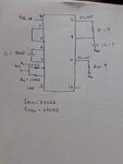
Upto this stage i only able to figure out below values

19814173_10213341526036431_1159825094_o.jpg

But how about designing low pass filter values. R3,C2 ? What values should i select in my case. Also no need to use SF_OUT right?
(Comparator 1 being using)
 
Last edited:

Personally, I would do this different way altogether. The 4046 seems an inefficient way of detecting if frequencies are within a range. You would be checking if the PLL had locked within the passband. You can do this with an NE567 or similar which is designed for that purpose or even by selective filtering and rectification.

Brian.

- - - Updated - - -

Personally, I would do this different way altogether. The 4046 seems an inefficient way of detecting if frequencies are within a range. You would be checking if the PLL had locked within the passband. You can do this with an NE567 or similar which is designed for that purpose or even by selective filtering and rectification.

Brian.
 

Hello Biran,

Earlier i used LM567. But it didn't properly worked. Also i have seen some videos 567 decoder is not going to lock. It simply gives an output when it detects a certain frequency. Also most of the applications LM567 used for certain frequency. But in my case there's a pass band range from 350Hz-550Hz.
 

Maybe you should consider a different approach: for example small computer (like raspberry pi) with piece of software (python + some libs) doing a FFT in a real time. What do you want to achieve in your project?
 

Hello filip.amator,

Actually im trying to detect mosquito frequencies. Simply i need to identify the presence of a mosquito. So i already identified the mosquitoes fundamental frequency range(There's no exact value, different mosquito's has different fundamental frequencies. I identify the range by using MATLAB FFT) . What im trying to do is when mosquito fly near to microphone if the wing beat tone is inside the capture frequency range it should identify there's mosquito and trigger micro controller. At that point MCU start to sample. So somehow fft will be working inside micro controller. This is a device which going place outside. So all the the time fft cannot be done. So what im doing is by using a pll it will trigger Microcontroller. That's my project
 

Hi,

Regarding frequency divider...I was thinking about another PLL chip with minimum VCO frequency of some 100kHz.
Sorry. The 4046 is able to generate frequencies in your desired range without frequency divider.

You say a continous FFT is not possible...I don't understand why.

I doubt the PLL solution will work satisfactory. You need slow filters after phase comparator, but you may want faster lock time...and the filter needs to be fast enough to track the varying frequency.
Somewhere in the datasheet it says bot PC inputs need to be 50% duty cycle. Can you ensure this?

Did you try a high order band pass filter? And something to check on enough output signal voltage.

Klaus
 
Status
Not open for further replies.

Similar threads

Part and Inventory Search

Welcome to EDABoard.com

Sponsor

Back
Top