Continue to Site

Welcome to EDAboard.com

Welcome to our site! EDAboard.com is an international Electronics Discussion Forum focused on EDA software, circuits, schematics, books, theory, papers, asic, pld, 8051, DSP, Network, RF, Analog Design, PCB, Service Manuals... and a whole lot more! To participate you need to register. Registration is free. Click here to register now.

5amp power supply troubleshooting

Status
Not open for further replies.

Enzy

Advanced Member level 1
Joined
Mar 20, 2016
Messages
488
Helped
2
Reputation
4
Reaction score
2
Trophy points
18
Activity points
4,607
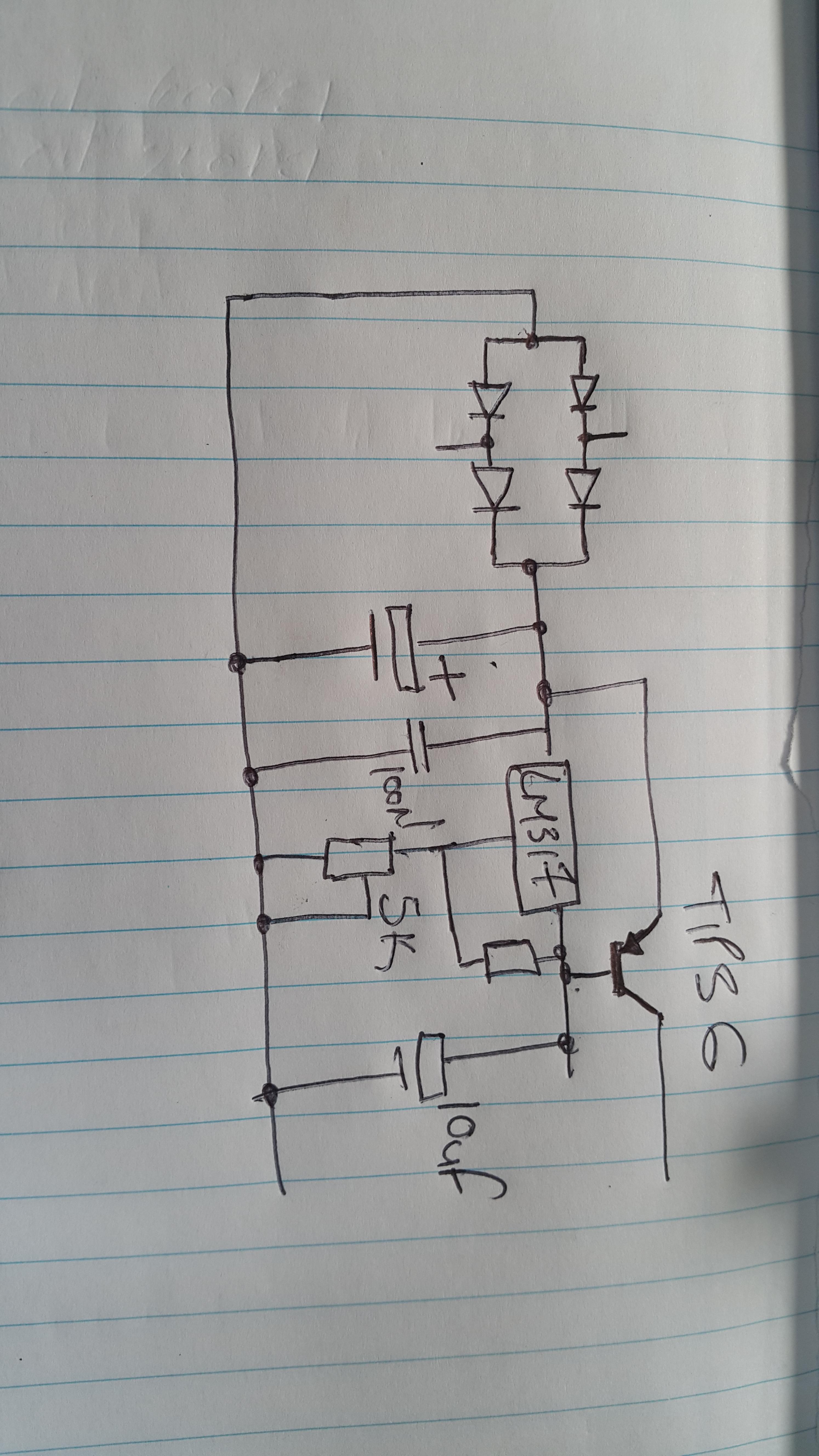
I built this circuit and for some reason the output transistor keeps getting hot.

the load is a tv which requires 12v @ 4 amps and the supply can supply 4.5v to 15v dc at 5amps


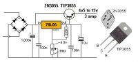
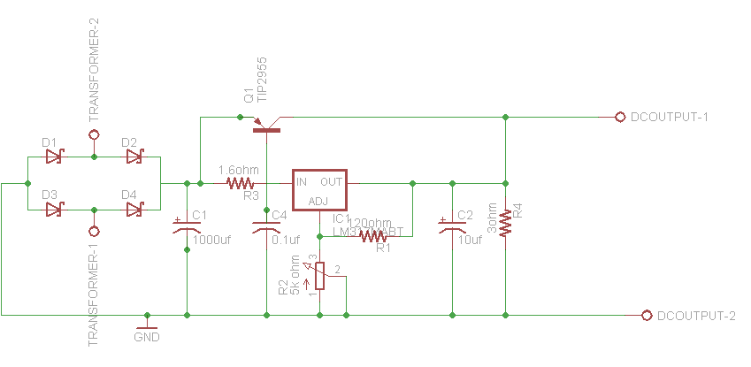
here is the schematic

based on my testing the tv is pulling 1.5amps when its loaded though the voltage pulls down from about 12,2v to about 9.8v but its only pulling 1.5amps.

the voltage regulator stays kool so I dont know if its something thats wrong with the design.
 

Hi,

P_tot = I x U = 1.5A x (12.2V - 9.8V) = 3.6W.
For sure it becomes warm .... without heatsink it's getting hot, I even assume too hot to survive.

What's the regulator minimum (ripple) input voltage?
You may need up to 5V more than the expected output voltage for the circuit to work properly.

Klaus
 

The heating is normal but the PSU design is far from optimal.
The 78L05 can be used as a variable regulator but it isn't designed to be one and it's current output rating is too low for that circuit anyway.
You will get better results by changing it to a dedicated adjustable device such as the LM317 and wrapping a PNP power transistor around it.

At the moment you have a poorly regulated output from the 78L05 with the transistor acting as a voltage dropper and current amplifier, there is nothing to stabilize the output or protect it from overload. Adding one resistor, changing the regulator type and transistor type will improve the regulation and provide thermal and over-current protection in go go.

Brian.
 

OK i made a sketch to reflect that
 

The original design is flawed. It is connected like a 317 although it is a 78L05. In any case that configuration will not work correctly. The usual current booster design uses a PNP bypass like shown below. If you don't use the L (low power) type regulator, then the 180 Ohm resistor can be made smaller to pass more of the current through the regulator itself.
 

Attachments

  • 12_reg.png
    12_reg.png
    17.5 KB · Views: 105
  • 12_reg1.png
    12_reg1.png
    17.6 KB · Views: 97
  • Like
Reactions: Enzy

    Enzy

    Points: 2
    Helpful Answer Positive Rating
OK i made a sketch to reflect that...

I cannot figure out how it works; you have no way to regulate the output.

The power transistor acts as a bypass; the circuit embedded in the regulator makes sure that the output voltage is correct. The base must get the correct bias and the regulator must adjust the output by adjusting the current share.

Linear regulator at high current gets hot; what is the input and output voltage?
 

I concur and apologize if I didn't fully explain it.

The top schematics in E-design's post are what I intended and you can see the deficiency of the NPN circuit straight away.
By using the PNP and adding the extra resistor at the input of the regulator you get three benefits:
1. more of the input voltage is available at the output (less dropped by the circuit)
2. output voltage regulation is better as the load changes
3. the overload and thermal protection in the regulator also shuts the transistor down.

The way it works is the regulator carries all the current until the voltage dropped across the input resistor is enough to bias the transistor into conduction. The transistor then takes over to carry any further load current. You decide the resistor value based on the current you want to limit the regulator to handle. Personally, I would use a lower value than 180 Ohms so the regulator carried say the first 0.5Amps. The value would be approx Vbe/Ireg so for 0.5A in the regulator it would be 0.8/0.5 = 1.6 Ohms. Mount the regulator and transistor on the same heat sink so the thermal shutdown sensor of the regulator also observes the transistor temperature.

Brian.
 
  • Like
Reactions: Enzy

    Enzy

    Points: 2
    Helpful Answer Positive Rating
Personally, I would use a lower value than 180 Ohms so the regulator carried say the first 0.5Amps

I made the resistor 180 Ohms because it was not clear which package he will be using. This will limit the current to under 100 mA for the L type. With the standard package, the resistor value can be sized down accordingly.
 

The usual current booster design uses a PNP bypass like shown below. If you don't use the L (low power) type, then the 180 Ohm resistor can be made smaller to pass more of the current through the regulator itself.

OK so I can use the Pnp design below and and by using a lower value resistor to pass more current through the regulator I can gain more power from the output transistor? Would it make sense to Parrallel 2 tip36 to ensure I can get atleast 5 amps output at 12v
 

You should be able to configure it to pass at least 0.5 A through the 317, and the rest could be handled by a single TIP36. What is your maximum input DC voltage? Both devices will need to be on a suitable heat-sink.
 

ok can I use a lm338T instead of the lm317?
 

The 338 is just a higher current version. You can use it the same way as the 317.
 

The original design is flawed. It is connected like a 317 although it is a 78L05. In any case that configuration will not work correctly. The usual current booster design uses a PNP bypass like shown below. If you don't use the L (low power) type regulator, then the 180 Ohm resistor can be made smaller to pass more of the current through the regulator itself.

is Am1 and Am2 diodes? or is it just showing current flow?

Ill use a Pot at the adj leg of the Lm338T
 

The original design is flawed. It is connected like a 317 although it is a 78L05. In any case that configuration will not work correctly. The usual current booster design uses a PNP bypass like shown below. If you don't use the L (low power) type regulator, then the 180 Ohm resistor can be made smaller to pass more of the current through the regulator itself.

It must be an instructables circuit. Some circuits are borderline OK, but many are very deficient circuits which clearly show that the "designer" has never bothered to read an actual datasheet or app note.


I made that drawing Im not sure about the connection from R4 to Dc output1 is it suposed to be joined?

- - - Updated - - -


I made that drawing Im not sure about the connection from R4 to Dc output1 is it suposed to be joined?
 

Of course! How else the regulator can see the voltage at the end of the output?

But how about the base connection for the pass transistor?

R4 is too small; did you miss the k?
 

What about the base connection? It is made at the input of the regulator.

sorry Ill change R4 value to 3k

- - - Updated - - -

I tested the circuit just now with a 12v transformer and I got 15VDC out but no adjustment from the 5k pot
 

The 3 Ohm resistor in my circuit is just a test load, which will be provided by the TV in your case. It is not part of the practical circuit.

You haven't told us what is the maximum DC input you working with.

If you are not getting adjustment, double-check your connections for mistakes. Get the regulator to work normally without the PNP or any load connected first. Then you can connect the PNP transistor and test with a suitable load.

Your rectifier filter capacitor must be sized according to the amount of ripple you can tolerate on the input to the regulator. You don't want the regulator to drop out of regulation at high-output currents. The 317 needs the input at least 3 V higher than the set output voltage. So, for 12 V out, you must not allow the input to dip below 15 V at maximum current load.

Look at this for an idea to calculate the correct value.
https://www.electroschematics.com/7048/capacitor-input-filter-calculation/

I think 1000 uF will be way to small for what you want to do.
 

I'm using a 200va 12v transformer 16.6 amps at the input, I'm using some 6 amp Diodes I didn't have any bread board to test the circuit so I just made a pcb so I'm sure the connections are correct, however I guess the mistake would be the 3k resistor that I included

- - - Updated - - -

Im at work where I used another transformer, I'm not sure of the power rating though... I'm getting 10.34v at the output of the circuit I got 12.5v if I adjust the pot in one direction fully if i fully turn it to the other direction I get 13.35v.
No load testing
 

What about the base connection? It is made at the input of the regulator.

The base is the switch handle; you set the voltage and a small current flows and the transistor turns on.

There are two kinds of beasts here: PNP and NPN- you need to use PNP only (why?)

The emitter and the base are connected to the input side- via a resistor (else both will be at the same potential and will be useless).

As current passes via the regulator, there will be voltage drop and this will slowly turn on the transistor. And as this gets turned on, some current passes through the pass transistor (obvious, right?)

If the potential at the output tries to increase, the regulator reduces the current to decrease the voltage (vice-versa) and the pass transistor is also regulated. Hence you must choose the base resistor carefully (important).

I tested the circuit just now with a 12v transformer and I got 15VDC out but no adjustment from the 5k pot

No adj from the 5k pot is clear- you have other mistakes.
 

Status
Not open for further replies.

Similar threads

Part and Inventory Search

Welcome to EDABoard.com

Sponsor

Back
Top