Continue to Site

Welcome to EDAboard.com

Welcome to our site! EDAboard.com is an international Electronics Discussion Forum focused on EDA software, circuits, schematics, books, theory, papers, asic, pld, 8051, DSP, Network, RF, Analog Design, PCB, Service Manuals... and a whole lot more! To participate you need to register. Registration is free. Click here to register now.

sg3525 error amplifier

Status
Not open for further replies.

ymmen

Member level 1
Joined
Nov 4, 2014
Messages
35
Helped
0
Reputation
0
Reaction score
0
Trophy points
6
Activity points
244
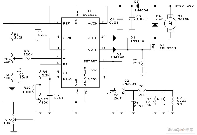
why do i get constant 5.84 v output as long as inverting input is less than non invertinginput and 0 as soon as inverting pin is equal or greater than non inverting input in sg3525 ic? Can i get internal circuit of how error amplifier is made?
 

1)5.84 volts out of where??
2)The data sheet has the schematic of the internals. You probably would have known that if you had looked at it.
3) Do you have any feedback?
 

1)5.84 volts out of where??
2)The data sheet has the schematic of the internals. You probably would have known that if you had looked at it.
3) Do you have any feedback?
instead of feedback i gave pin 2 the reference voltage 5.1V from pin 16 and was varying pin1 from 0 to 5v to check the output of error amplifier which is pin 9 of the ic.but the 9th pin constantly gives 5.8V Unless i reach 5.1V where the output of 9th pin suddenly drops from 5V to 0.
Can u explain me this behaviour, moreover can you suggest a method through which i could know the behaviour of error amplifier to different 'voltage inputs

Thank you..
 

The inputs that of an Op Amp while Comp is the output, and with no negative feedback, it will act like a comparator.

sg3525.jpg
Thus it is "logical" that Output and Comp will be low when Inv=high and visa versa. As with all OA's, the differential inputs will always be zero when output is in the linear range.
 
  • Like
Reactions: ymmen

    ymmen

    Points: 2
    Helpful Answer Positive Rating
i got thatt. Sir can u plz explain me how the error amplifier will work in linear region if we set up feedback?
 

4565491400_1351804326.jpg

Connect this way. Tie pin9 andpin1 together. Apply control voltage on pin2.
 

To check error amplifier working in linear region i connected 2.2k bbetween pin 1 and pin 9 and gave 3.3v through 1k resistor to pin 1. I should get a gain of 2.2 as gain is rf/rg.but iam not getting it, is there any explanation for it?
 

May be saturation. Hows pin 2 connected? Observed Pin 9 voltage?
 

Error amp is connected to another amp which has its own gain. Try with voltage from near 2.5V on pin2.
 

You can skip error amp and directly apply voltage on comp pin to observe voltage range for full PWM variation.
 

bravo, error amplifier just wworks fine whewhen in the input is in range of 2.5 V and voltage difference between two pins being less than 0.5 V. But can anyone explain reason behind it?
 

What are you trying to achieve? The SG3525 error amplifier is designed to work in a feedback amplifier configuration in the specified input common mode range and an output voltage range corresponding to the PWM ramp.
 

bravo, error amplifier just wworks fine whewhen in the input is in range of 2.5 V and voltage difference between two pins being less than 0.5 V. But can anyone explain reason behind it?

Can you figure out how plot the gain? It is a differential amplifier.

Maybe you have a sweep signal you can inject from an MP3 player and you can figure out how to make it into a power amp for a speaker, You are close to learning how to measure closed loop stability response called Bodé Plots, other pro's haven't tried yet.

Of course if you have a <100mV slow square wave or small impulse injected in here with a similar resistor to the input of (-), now you see the time domain, stability response which is related.
 

is adding a capacitor in parallel to resistor between 1 and 9 pin related to bode plots oor gain?
 

Both in case of doubt. Bode plot means sketching the gain versus frequency as phase and magnitude.
 

Status
Not open for further replies.

Part and Inventory Search

Welcome to EDABoard.com

Sponsor

Back
Top