Continue to Site

Welcome to EDAboard.com

Welcome to our site! EDAboard.com is an international Electronics Discussion Forum focused on EDA software, circuits, schematics, books, theory, papers, asic, pld, 8051, DSP, Network, RF, Analog Design, PCB, Service Manuals... and a whole lot more! To participate you need to register. Registration is free. Click here to register now.

Help in Verilog Code: Timing Diagram Showing wrong result

Status
Not open for further replies.

AbinayaSivam

Member level 1
Joined
Jul 27, 2017
Messages
38
Helped
0
Reputation
0
Reaction score
0
Trophy points
6
Activity points
345
Hi,

No Compilation error but logic of timing diagram is wrong.
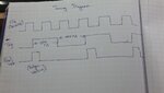
I am generating Trigger signal for 500ns, and every neck edge (either positive or negative) of Trigger i am trying to store the counter in Register. Can anyone verify me code. I have simulated verilog Code in Quartus but in NIOS i am getting incorrect result.
Code:
module Counter(
    input clk,                                      // Clk 50Mhz
	 input enable,
    input reset,
    output reg[31:0] Final_value
   // output wire trig
    );
    reg[31:0] counter_out;
    reg [7:0] temp=0;
    reg [31:0] counter_result;
    wire temp1;
    wire temp2; 
	 reg trig;
       
   always@(posedge clk or negedge reset)
   begin
    if(~reset)
        begin
        trig<=0;
        temp<=0;
        counter_out<=0;
        end
    else if (enable==1'b1)                                   // Condition
        begin
        counter_out<=counter_out+1;                // Making delay 
        temp<=temp+1;
        if(temp==25)
            begin
            temp<=0;
            trig<=~trig;                              // Generating Trigger Signal for 500ns
            end
		  end
  end 

	 assign temp1=trig;
	 assign temp2=temp1&&clk;
	 always@(posedge temp2 or negedge reset)
	 if(~reset)
	    counter_result<=0;   
	  else 
	 begin
        counter_result<=counter_result+1;             // Generating Counter Data
     end
  always@(posedge trig or negedge reset)
  if(~reset)
       Final_value<=0;  
   else 
  begin
       Final_value<=counter_result;                        // Collecting Edge value of Trigger signal into Regsiter [Final_value]
  end
endmodule

Please verify my code whether it is right or wrong.
 

Hi,

so why don´t you show us the "wrong" timing diagram?

And please try to give complete informations. How can we check the timing when you don´t tell us the clock frequency?

Klaus
 

Sorry, It is not "wrong" timing diagram.

I need to store neck edge (Positive) data once. Please find the attachment.
Timing_diagram.JPG

I have compiled that Code in Altera.
Nios.JPG

Counter data like 0, 27,54, 81 is repeating for long time. I need to collect those data only once. Please tell me how it can be possible.
Thanks
 

Hi,

I still don´t see clock frequency.

And I still don´t know what is wrong and how you want it to be.

--> please give your clock frequency
--> please draw a timing diagram of the signals how you want them to be.

Klaus
 

>>please give your clock frequency
50 MHZ

Verilog code is correct as of now. But i need some modification to be done like positive edge detector. I want to collect only data of Positive(neck) edge of trig signal and store into register.

- - - Updated - - -

Timing Diagram

I need to collect Final_result (From counter_result data) only at positive edge of trigger signal.
 

Attachments

  • 20180918_152128.jpg
    20180918_152128.jpg
    368.4 KB · Views: 128

Hi,

You can´t (want?) draw a timing diagram...

At least to me... It´s a riddle:
You say code is correct.... but then you say it needs to be modified..
What do you mean with "collect"?
What do you mean with "data"? There´s do "data" in your code. Which data? What´s the name?
What do you mean with "neck"? There´s do "neck" in your code.
What do you mean with "register"? What´s it´s name? Where did you define it?


Klaus
 

Please you through the NIOS console (Previous). Why same data is printing for some times in console?
 

Hi,

Sorry, I tried a couple of times to get informations. Still it´s unclear to me.
I give up.
I hope that another member is able to help you.

Klaus
 

A poor understanding of digital design techniques is the base problem in this instance. Using an FPGA to perform gated clocks, creating logic generated clocks are both bad design techniques in FPGAs. These techniques are typically avoided, by experienced engineers, only those who have a firm understanding of all the "gotchas" have a chance of getting these kinds of designs working over pvt.

Your waveform shows that your trig signal is more than one clock cycle wide, so what do you expect when you gate the clock with this signal and generate a gated clock that has more than a single rising edge. In the real world on real hardware you will more than likely have a clock glitch produced due to timing changing between the pvt corners.
 

Hello,

Through Verilog Code

1. Generating Trigger signal (trig) for 500ns
2. Generating Counter data

I need to collect the counter data only at Positive edge (at the rising edge alone) of Trigger signal (not at the entire Positive cycle of Trigger signal). How can be possible.

I have tried but i am not able to
Code:
assign temp1=trig;

	 assign temp2=temp1&&clk;
	 always@(posedge temp2)
	 if(reset)
	    counter_result<=0;   
	  else 
	 begin
        counter_result<=counter_result+1;
     end
   assign detect = trig & ~temp1;               //// (at the rising edge alone) of Trigger signal
   always@(posedge detect)
   if(reset)
   Final_value<=0;  
   else 
   begin
   Final_value<=counter_result;
   end
   
endmodule
 

The following code is not giving the correct results!

Modified Code
Code:
always @ (posedge clk) 
     begin
      temp1 <= trig;
     end
  assign detect = trig & ~temp1;                    /// EDGE DETECT
  assign temp2=temp1&&clk;
 always@(posedge temp2)
      if(reset)
         counter_result<=0;   
       else 
      begin
         counter_result<=counter_result+1;
      end
   always @(posedge clk) 
   begin
    if(reset)begin
    Final_value<=0; 
    end 
    else if (detect)
    Final_value<=counter_result;
   end
  endmodule
Timing_Diagram.JPG

I want to collect the data (Final_value) only at edge-detect (detect). But in timing diagram, Final_value (data) is showing for full Positive cycle.
 

Status
Not open for further replies.

Part and Inventory Search

Welcome to EDABoard.com

Sponsor

Back
Top