Continue to Site

Welcome to EDAboard.com

Welcome to our site! EDAboard.com is an international Electronics Discussion Forum focused on EDA software, circuits, schematics, books, theory, papers, asic, pld, 8051, DSP, Network, RF, Analog Design, PCB, Service Manuals... and a whole lot more! To participate you need to register. Registration is free. Click here to register now.

questions about eye diagram of transimpedance amplifier

Status
Not open for further replies.

ultrasonic.1991

Member level 3
Joined
Nov 6, 2015
Messages
60
Helped
0
Reputation
0
Reaction score
0
Trophy points
6
Activity points
554
hi i designed a transimpedance amplifier for 10 Gbps application with cadence. i simulated eye diagram and it seems right but i have some questions about it .
1-in the book "Design of integrated circuits for optical communications" by behzad razavi says "optimal bandwidth is 0.7*rb that means 7 GHz for 10 Gbps and decreasing bandwidth reduces both vertical and horizontal eye opening" but for my circuit when bandwidth in process corners ss and tt decreases down to 4 and 5 GHz from 7.8 GHz nominal the vertical eye opening increases from 5.3 mv-pp to about 7 mv-pp and only horizontal eye opening decreases.why is that ?
2-the input current amplitude is 20 uA p-p in sonnet oc-192 standard and thats the amplitude of current random bits that i applied to my circuit and simulated eye diagram with. the transimpedance gain is 53.6 db ohm and that means i should have a 9.57 mv-pp output but the eye opening is 5.3 mv-pp and the difference between best "1" and best "0" is 12 mv-pp why ?
3- how much vertical eye opening is necessary for 10Gbps tia ? by what i read about eye diagrams and tia papers i think horizontal eye opening should be less than bit period is this true ? what should be the minimum and maximum of horizontal eye opening ?
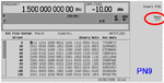
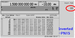
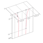
i attached the eye diagrams for nominal , SS 80 degrees corner ,TT 80 degrees corner Respectively . if you answer any of my questions it would be really helpful .

nominal_eye.png
ss_80_eye.png
tt_80_eye.png
 

hi i designed a transimpedance amplifier for 10 Gbps application with cadence.
What do you mean by "with cadence" ?

but for my circuit when bandwidth in process corners ss and tt decreases down to 4 and 5 GHz from 7.8 GHz nominal
How do you evaluate bandwidth ?
If you use AC Analysis, it is not appropriate.

the transimpedance gain is 53.6 db ohm
How do you evaluate gain ?
If your gain is a value at specific frequency by AC Analysis, it is not appropriate.

how much vertical eye opening is necessary for 10Gbps tia ?
It depends on required BER.

what should be the minimum and maximum of horizontal eye opening ?
It depends on required BER.


BTW, you have to evaluate eye opening as relative value.
See https://www.designers-guide.org/Forum/YaBB.pl?num=1209812189

https://community.cadence.com/cadence_blogs_8/b/cic/posts/virtuosity-eye-diagram-measurements
 
Last edited:
Show me frequency characteristics of gain with x-axis as frequency by AC Analysis.
Over plot three cases.
 

What do you mean by "with cadence" ?
i'm sorry i should have been more specific. i use eye diagram function from calculator tab of cadence virtuoso analog design environment.
How do you evaluate bandwidth ? If you use AC Analysis, it is not appropriate.
i copied the circuit into another circuit where i can apply isin for input .and yes i use ac analysis for bandwidth and then i plot output and calculate exact 3 db bandwidth with trace marker . what else way can i calculate bandwidth ?
If your gain is a value at specific frequency by AC Analysis, it is not appropriate.
no the circuit should have a constant gain from zero hertz to 7 GHz and that's the frequency sweep i use .
for BER 10^-12 should be fine .in the first link that you sent talks about time aperture and amplitude aperture that are not really common and are not my goal and i saw the second link you added in the end . it seems a really useful tool but after plotting eye diagram when i go to measurement tab this shows up
Screenshot-5.png
and when i click ok or apply nothing happens
 

i use ac analysis for bandwidth
and then i plot output and calculate exact 3 db bandwidth with trace marker.
...........................................................
no the circuit should have a constant gain from zero hertz to 7 GHz
You can not understand fundamental transmission theory at all.
Such bandwidth has no meaning for DUT which has non flat at passband.

Show me frequency characteristics of gain with x-axis as frequency by AC Analysis.
Overplot three cases.

i saw the second link you added in the end .
it seems a really useful tool but after plotting eye diagram when i go to measurement tab this shows up
and when i click ok or apply nothing happens
I can not understand what you want to mean at all.

I think eye measurements are not available in your environment since your Design Framework is relative old.
And you use Cadence Wavescan not Cadence ViVA.

Do you have any other post processing tool ?
For example, Synopsys CosmosScope, Synopysis CustomWaveViewer, Keysight ADS, etc.
 
Last edited:

3case.jpg
this is the result you wanted. about eye measurement can't i do it with trace markers ?
for BER=10^-12 whats the minimum acceptable vertical and horizontal eye opening ?

- - - Updated - - -

Do you have any other post processing tool ?
For example, Synopsys CosmosScope, Synopysis CustomWaveViewer, Keysight ADS, etc.
i have access to Synopsys CosmosScope and ADS and matlab
you can not understand fundamental transmission theory at all.
Such bandwidth has no meaning for DUT which has non flat at passband.
first i appreciate your quick answers and i learned a lot from you second what is DUT ? third do you know what high frequency TIA is ? did you read any papers about TIA ? here are somethings that you could use
https://ieeexplore.ieee.org/document/8016342/
https://www.wiley.com/en-us/Design+...l+Communications,+2nd+Edition-p-9781118439456
 

this is the result you wanted.
You have to consider frequency components of bit stream, although I don't know a characteristics of $random() in "ahdlLib/rand_bit_stream".

See attached "E4438C_PN9.png" and "E4438C_PN15.png".
Many low frequency patterns are included.

For Rate=10Gbps, dominant frequeny component is followings.
"1010" : 5GHz
"11001100" : 2.5GHz
"111000111000" : 1.67GHz

See https://www.edaboard.com/attachment.php?attachmentid=148256&d=1533122963

Result of your vertical eye opening is not contradictory with frequency characteristics of Gain at all.

about eye measurement can't i do it with trace markers ?
What do you want to mean ?
Describe sentences correctly.

for BER=10^-12 whats the minimum acceptable vertical and horizontal eye opening ?
Evaluate following two Bathtub Curves by yourself.

- Timing Bathtub Curves
- Voltage Bathtub Curves

i have access to Synopsys CosmosScope and ADS and matlab
See the followings.
https://edadocs.software.keysight.com/pages/viewpage.action?pageId=6064628
https://www.ece.tamu.edu/~spalermo/ecen689/ECEN720_lab6_2014.pdf

https://www.mathworks.com/content/d...ntel/june-2014-bathtub-curve-presentation.pdf

However you can build custom function even in Cadence Design Framework by Skill Language, if you can understand Bathtub Curve and Skill Language.

second what is DUT ?
What do you want to mean ?

third do you know what high frequency TIA is ?
did you read any papers about TIA ?
TIA is no more than current input amplifier.
There is no special topics.

Post thread after understanding fundamental transmission theory.

And you don't consider noises at all.
Internal Noise : Device Thermal Noise, Device Fricker Noise
External Noise : Noises Power Lines(Vdd, Gnd)
 

Attachments

  • E4438C_PN9.png
    E4438C_PN9.png
    77.2 KB · Views: 138
  • E4438C_PN15.png
    E4438C_PN15.png
    78 KB · Views: 122
  • 180804-162412.png
    180804-162412.png
    87.2 KB · Views: 134
  • 180804-162502.png
    180804-162502.png
    68.4 KB · Views: 133
  • 180804-162538.png
    180804-162538.png
    61.1 KB · Views: 126
Last edited:
thanks , so i should generate voltage bathtub curves for determining minimum vertical eye opening and timing bathtub curve for horizontal eye opening with ads i read somewhere that i should use both cadence and ads to generate bathtub curve from eye diagram is that correct then how should i do it ? because i didn't see any instruction for this anywhere. should i export my circuit to a s2p file from cadence or should i build the circuit again in ads ?
 

It is very difficult to read your sentences.
Write gramatically corect sentences.

i read somewhere that i should use both cadence and ads to generate bathtub curve from eye diagram is that correct then how should i do it ?
What do you want to mean ?

because i didn't see any instruction for this anywhere.
Surely search.
There are too many instructions, although it is very easy task.

should i export my circuit to a s2p file from cadence
Can you understand "s2p file" ?
Why do you refer "s2p file" ?

or should i build the circuit again in ads ?
I don't do such thing.

Dump waveform as CSV file in Cadence Post Processing Environment.
Add header and footer to CSV file as MDIF.
You can read MDIF in ADS.
https://edadocs.software.keysight.com/display/ads2009/Working+with+Data+Files

There are two methods to evaluate EYE in ADS.
(1) Use Eye_probe in Schematic, here re-run transient analysis in ADS by using datafile read source.
(2) Use data display, without re-run transient analysis

I choose (2), although (1) is easy for EYE evaluation, since we can use Eye_probe.

Example of MDIF
Code:
! Fixed Manchester Code (Rbit=1.0bps, Length=17bit)
BEGIN
% time(real)  data(real)
0.05	1
0.5	1
0.55	0.0141254
1	0.0141254
1.05	0.0141254
1.5	0.0141254
1.55	1
2	1
2.05	1
2.5	1
2.55	0.0141254
3	0.0141254
3.05	0.0141254
3.5	0.0141254
3.55	1
4	1
4.05	1
4.5	1
4.55	0.0141254
5	0.0141254
5.05	0.0141254
5.5	0.0141254
5.55	1
6	1
6.05	1
6.5	1
6.55	0.0141254
7	0.0141254
7.05	0.0141254
7.5	0.0141254
7.55	1
8	1
8.05	1
8.5	1
8.55	0.0141254
9	0.0141254
9.05	0.0141254
9.5	0.0141254
9.55	1
10	1
10.05	0.1
10.5	0.1
10.55	1
11	1
11.05	0.1
11.5	0.1
11.55	1
12	1
12.05	0.1
12.5	0.1
12.55	1
13	1
13.05	0.1
13.5	0.1
13.55	1
14	1
14.05	0.1
14.5	0.1
14.55	1
15	1
15.05	0.1
15.5	0.1
15.55	1
16	1
16.05	0.1
16.5	0.1
16.55	1
17	1
END
 
Last edited:

i exported eye diagram to a csv file and then added header and footer and changed the format to mdif as you said.but when i try to read data file into data set it gives error .i attached a pic from the error .Screenshot-6.png by the way i tried to analyse eye diagram in matlab and i use eyescope function in matlab with the data saved in csv file .but when i want to use eye diagram toolbox in matlab it doesn't identify the eye diagram i plotted with matlab as eye diagram object .
 

i also tried importing netlist file with ads it gives me the following errors :

Warning detected by hpeesofsim during netlist parsing.
In file `/usr/local/flexlm/ADS_tsmc013um/tsmc_cm013rf_v1.7//circuit/models/rf013.net' at, or just before, line 2691.
Subcircuit `rppolyhri_rf' is redefined. Discarding the earlier definition
from `/usr/local/flexlm/ADS_tsmc013um/tsmc_cm013rf_v1.7//circuit/models/rf013.net:2599'.
Error detected by hpeesofsim during netlist parsing.
ADS-syntax parser error in `<string/GEMX netlist>', line 144:
syntax error

Simulation terminated due to error.
--------------------
i tried with ads 2009 and ads 2011 both of them gives the second parser error

- - - Updated - - -

in ads 2011 it gives the following error
error detected by hpeesofsim during netlist parsing.
ADS-syntax parser error in `<string/GEMX netlist>', line 3:
syntax error
 

i exported eye diagram to a csv file and then added header and footer and changed the format to mdif as you said.but when i try to read data file into data set it gives error .i attached a pic from the error .View attachment 148492 by the way i tried to analyse eye diagram in matlab and i use eyescope function in matlab with the data saved in csv file .but when i want to use eye diagram toolbox in matlab it doesn't identify the eye diagram i plotted with matlab as eye diagram object .

i should correct this i figured out that i should use data items toolbox and i used s2pmdif from the pallet it gives an error that says : Error detected by hpeesofsim during netlist flattening.
While evaluating expression `S2P1.CMP1.All':
File `/home/eslam/Desktop/eye11.mdif' read error: File format error detected: required ACDATA block is not specified in the file. Check that the selected file type is correct
Errors detected while trying to read the data file..
 

Hi,

what is DUT
--> Device Under Test.
This is a very common abbreviation in testing area.

Klaus
 

Status
Not open for further replies.

Part and Inventory Search

Welcome to EDABoard.com

Sponsor

Back
Top