Continue to Site

Welcome to EDAboard.com

Welcome to our site! EDAboard.com is an international Electronics Discussion Forum focused on EDA software, circuits, schematics, books, theory, papers, asic, pld, 8051, DSP, Network, RF, Analog Design, PCB, Service Manuals... and a whole lot more! To participate you need to register. Registration is free. Click here to register now.

[SOLVED] Using N-Channel MOSFET as switch to drive a resistor load

Status
Not open for further replies.

ignition

Junior Member level 1
Joined
Oct 14, 2012
Messages
18
Helped
0
Reputation
0
Reaction score
0
Trophy points
1,281
Activity points
1,404
Hi

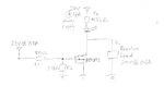
I m trying to drive a resistor (dummy) load rated 24V, 0.6A using a Infineon BSP295 N-MOSFET (Attached).

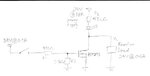
A power supply is used to provide power to the circuit. A 3.3V regulator rated at 0.3A is connected to the switch then to a voltage divider before connecting to the gate. When the switch is closed, a voltage divider gives 3V to the gate. The current drawn at the initial phrase goes up to 0.6A for about 5 secs, before slowly reducing to 10mA, as if the MOSFET is not conducting. This is happening consistently.

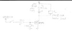
In another implementation, the 24V is connected to the switch, a voltage divider before connecting to the gate. The voltage divider gives 13V to the gate when the switch is closed. Again, the current drawn at the initial phrase goes up to 0.6A for a longer time of about 10 secs, before slowly reducing to 10mA, as if the MOSFET is not conducting in a consistently manner.

What is wrong with my controlling of the MOSFET?
 

Attachments

  • Infineon-BSP295-DS-v02_03-en.pdf
    442.5 KB · Views: 143

Hi

I have attached the circuit schematics.
Thanks

- - - Updated - - -

Here is the schematics
 

Attachments

  • Schematics.jpg
    Schematics.jpg
    20.3 KB · Views: 203

May be your measurements have been made with a different circuit? By design (4.7k resistor), the load current is limited to about 5 mA in the shown circuit.
 

May be your measurements have been made with a different circuit? By design (4.7k resistor), the load current is limited to about 5 mA in the shown circuit.

The branch where the LED resides should be drawing 5mA, the branch the load is connected should draw 0.6A if the MOSFET is operating properly as a switch
 

Hi,

I´m not sure what you want to achieve...

Maybe try to connect the load to 24V instead of GND.


Klaus

Hi

I am trying to use a MOSFET as a switch and a resistor load is used to simulate the actual device I am controlling.
A on/off switch is used to operate the load. Closing the on/off switch will operate the load and vice versa. Hope this gives a clearer picture. Also I re-attach the schematics to include the on/off switch at the gate.
 

Attachments

  • Schematics.jpg
    Schematics.jpg
    23.1 KB · Views: 152

Hi,

I´m not sure what you want to achieve...

Maybe try to connect the load to 24V instead of GND.


Klaus

- - - Updated - - -

Hi,

in your circuit...
* the LED path will limit the LOAD current to max. 5mA. Not possible to draw more than this.
* the LED is always ON
* the LOAD current is about 5mA when FET is OFF
* the LOAD current is about 0mA when FET is ON


Klaus
 

Hi

I reconfigured the circuit to the attached.

I am still seeing the current drawn slowly dropping from 0.6A
 

Attachments

  • Schematics.jpg
    Schematics.jpg
    23.7 KB · Views: 166

Hopefully the schematic is correct now.

Presumed it is, I guess it's either a dropping supply voltage, or a resistor with PTC characteristic. For clarification, you would measure the different circuit node voltages in operation.

Heating of the MOSFET has basically an opposite effect, Vth is decreasing with rising junction temperature.

Your claim to have measured 0.6 A in the original circuit still raises doubts about your reported results.

One thing I noticed was the decreasing of VDS from ~0.2V to 0V.
The MOSFET should be able to handle 0.6A with ease in room temperature
 

Hi,

switch your MOSFET ON and then measure the voltage directely across pin1 and pin3 of your MOSFET with a DVM. What does it show?


Klaus
 

One thing I noticed was the decreasing of VDS from ~0.2V to 0V.
O.K., so it's not the MOSFET turning the current down. Either the load itself, or the power supply, can be easily measured.

How about the indicator LED?
 

Hi,

One thing I noticed was the decreasing of VDS from ~0.2V to 0V.
What exactely is your load? 24V and 0.6A gives a lot of heat....

The MOSFET should be able to handle 0.6A with ease in room temperature
It is no 3.3V logic level MOSFET. --> It is not very saturated with your V_GS.

Klaus
 

O.K., so it's not the MOSFET turning the current down. Either the load itself, or the power supply, can be easily measured.

How about the indicator LED?

Hi

Indicator LED is constantly lit up.
 

Hi,


What exactely is your load? 24V and 0.6A gives a lot of heat....


It is no 3.3V logic level MOSFET. --> It is not very saturated with your V_GS.

Klaus

I can connect the gate to the 24V supply too. How much voltage should I inject to the gate?
 

Looks like the load is shutting down the current. What is it exactly? Could it be a PTC resistor or anything with internal regulation?
 

Hi,


What exactely is your load? 24V and 0.6A gives a lot of heat....


It is no 3.3V logic level MOSFET. --> It is not very saturated with your V_GS.

Klaus

The resistor used can handle 50W of power.
 

With a minimum PCB copper heatsink the Rja_th is 115'C/W and you are exceed the DC SOA curve spec figure 3 .

Even if 0.3 Ohm using 10V for Vgs, this part is under-designed. Your load is 12V/40 Ohms and the RdsOn of 0.3 and up is Vgs dependent. With 0.6A* 0.5Ohms or 0.3W the minimal heat sink will raise Tjcn by 0.3/115'C (or 'K) or more depending on copper area and Vgs and rise to >40'C above ambient. Possibly more with your naive design, thus the PTC effect on RdsOn causes more loss and thermal runaway causes it to overheat and drop current. Very bad design. Read about how to string 4or3V LEDs to 12 V with much lower RdsOn or much bigger heatsink and C. regulator with 50 mV current sense R and comparator to 12V Vgs. Good power White LEDs can draw 0.6A with 2.9V while poor quality ones are more like 3.2 or 3.4 depending on how cool they are and bin umber and thus ESR*If above 2.7V approx.

. Your mileage depends on your inexperience. read my other LEd answers and get with the program!
 

Your schematic wrongly shows the load AND the Mosfet both connected to ground then the Mosfet cannot apply 24V to the load. The load turns on the LED when the Mosfet is turned off.
 

Status
Not open for further replies.

Similar threads

Part and Inventory Search

Welcome to EDABoard.com

Sponsor

Back
Top