flote21
Advanced Member level 1
Hello folks!
I am trying to implement manually a 4 order FIR filter in a FPGA. Therefore I have a VHDL module which is able to generate a sinusoidal signal of whatever frequency with an amplitude which goes from 0 to 65535 (16 bits) designed previously with a script in matlab:
Sinusoidal Matlab script:
WaveGenerator.vhd module:
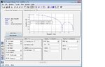
I used Matlab to design a low pass filter (see pic1 and pic2 attached)
I converted the fixed point coefficients into Q7 format
0.15939331054688 @ Q7 = 0x14
0.38282775878906 @ Q7 = 0x31
0.38282775878906 @ Q7 = 0x31
0.15939331054688 @ Q7 = 0x14
This is the code of the 4 order FIR VHDL filter:
After running the simulations in modelsim I always get a noisy output of the FIR filter for all the frequencies configured for the sinusoidal signal generated by the WaveGenerator.vhdl module (See pic3 with InputFreq=3.3MHz and pic4 with InputFreq=500KHz)
Anyone can tell me why is happening this issue??
Thanks in advance.
I am trying to implement manually a 4 order FIR filter in a FPGA. Therefore I have a VHDL module which is able to generate a sinusoidal signal of whatever frequency with an amplitude which goes from 0 to 65535 (16 bits) designed previously with a script in matlab:
Sinusoidal Matlab script:
Code:
N=100;
fs=200;
f=1;
ts=1/fs;
t = ts*(0:N-1);
x=0;
x=(((2^16)/2)-1)*sin(2*pi*f*t-pi/2);
x=(((2^16)/2)-1)+x;
x=round(x);
filename = 'SinusSignal.xlsx'
xlswrite(filename,x);
plot(t,x)
WaveGenerator.vhd module:
Code:
library IEEE;
use IEEE.STD_LOGIC_1164.ALL;
--use IEEE.STD_LOGIC_ARITH.all;
--use ieee.std_logic_unsigned.all;

-- Uncomment the following library declaration if using
-- arithmetic functions with Signed or Unsigned values
use IEEE.NUMERIC_STD.ALL;

-- Uncomment the following library declaration if instantiating
-- any Xilinx leaf cells in this code.
--library UNISIM;
--use UNISIM.VComponents.all;

entity WaveGenerator is
    Generic ( DEBUG     : BOOLEAN  := false;-- True for simulations
	          ROM_DEPTH : INTEGER  := 100); -- Number of items of the ROM
    Port    ( CLK         : in STD_LOGIC;   -- Input Clock
              RST         : in STD_LOGIC;   -- High level reset
              WAVE_GEN    : out STD_LOGIC_VECTOR (15 downto 0)); -- Waveform data output
end WaveGenerator;

architecture Behavioral of WaveGenerator is

-- Signals to generate the waveform
signal dataout     : unsigned (15 downto 0);
signal table_index       : integer range 0 to ROM_DEPTH;
signal table_index_down  : std_logic; -- table_index_down = '1' => walk down the table; ='0' walk up the table
--ROM for storing the table values generated by MATLAB for the
-- 1/4 of a sinus signal
type table_type is array (0 to ROM_DEPTH-1) of integer range 0 to 65535;
signal table : table_type :=(
     0    ,16   ,65	  ,145	,258  ,403  ,580  ,789  ,1029 ,1301 ,
	 1604 ,1937 ,2301 ,2695 ,3119 ,3571 ,4053 ,4563 ,5101 ,5666 ,
	 6258 ,6876 ,7520 ,8188 ,8881 ,9597 ,10336,11098,11881,12684,
	 13507,14349,15210,16087,16981,17891,18815,19754,20705,21668,
	 22641,23625,24618,25619,26627,27641,28660,29683,30710,31738,
	 32767,33796,34824,35851,36874,37893,38907,39915,40916,41909,
	 42893,43866,44829,45780,46719,47643,48553,49447,50324,51185,
	 52027,52850,53653,54436,55198,55937,56653,57346,58014,58658,
	 59276,59868,60433,60971,61481,61963,62415,62839,63233,63597,
	 63930,64233,64505,64745,64954,65131,65276,65389,65469,65518
	 );

begin

	--Process to generate the signal
	process(CLK,RST)
	begin
		if RST = '1' then
			table_index <= 0;
			table_index_down <= '0';
			dataout <= to_unsigned(table(0),dataout'length);
		elsif rising_edge(CLK) then
			-- walking the table
			if table_index_down = '0' then -- walk up the table
				if table_index < ROM_DEPTH-1 then
					table_index <= table_index + 1;
				else
					table_index_down <= '1';
					table_index      <= table_index;
				end if;
			else                           -- walk down the table
				if table_index > 0 then
					table_index <= table_index - 1;
				else
					table_index_down <= '0';
					table_index      <= table_index;
				end if;
			end if;
		dataout <= to_unsigned(table(table_index),dataout'length);
		end if;
	end process;

	-- Output of the SignalGenerator.
	WAVE_GEN <= std_logic_vector (dataout);


end Behavioral;
I used Matlab to design a low pass filter (see pic1 and pic2 attached)
I converted the fixed point coefficients into Q7 format
0.15939331054688 @ Q7 = 0x14
0.38282775878906 @ Q7 = 0x31
0.38282775878906 @ Q7 = 0x31
0.15939331054688 @ Q7 = 0x14
This is the code of the 4 order FIR VHDL filter:
Code:
library IEEE;
use IEEE.STD_LOGIC_1164.ALL;
-- Uncomment the following library declaration if using
-- arithmetic functions with UNSIGNED or UnUNSIGNED values
use IEEE.NUMERIC_STD.ALL;
use ieee.std_logic_unsigned.all; --unsigned arithmetics library
use ieee.std_logic_signed.all; --unsigned arithmetics library

-- Uncomment the following library declaration if instantiating
-- any Xilinx leaf cells in this code.
--library UNISIM;
--use UNISIM.VComponents.all;

entity FIR_FILTER_N2 is
    Generic ( DEBUG   : BOOLEAN  := false);              -- True for simulations
    Port ( CLK        : in STD_LOGIC;
           RST        : in STD_LOGIC;
           FILTER_IN  : in STD_LOGIC_VECTOR (15 downto 0);
           FILTER_OUT : out STD_LOGIC_VECTOR (15 downto 0));
end FIR_FILTER_N2;

architecture Behavioral of FIR_FILTER_N2 is

-- FIR coefficients.
type FIR_COEFF is array (0 to 3) of signed (7 downto 0);
signal B : FIR_COEFF;

-- Multiplication signals
type X_ARRAY is array (0 to 3) of signed (15 downto 0);
signal X : X_ARRAY;
type W_ARRAY is array (0 to 3) of signed (31 downto 0);
signal W : W_ARRAY;
signal Y : signed (15 downto 0);

-- FIR signals.
type MUL_ARRAY is array (0 to 3) of signed (31 downto 0);
signal MUL : MUL_ARRAY;

signal TAP_CNT : unsigned (7 downto 0);
signal Z1 : signed (31 downto 0);
signal Z2 : signed (31 downto 0);
signal Z3 : signed (31 downto 0);
signal ADD1 : signed (31 downto 0);
signal ADD2 : signed (31 downto 0);
signal ADD3 : signed (31 downto 0);

begin

----------------------Low pass filter 6kHz --> 12kHz -12 dB-----------------
-- Coefficients assigments
-- B(0) <=  "11110111";
-- B(1) <=  "00001001";
-- B(2) <=  "00100110";
-- B(3) <=  "00110011";

B(0) <=  x"14";
B(1) <=  x"31";
B(2) <=  x"31";
B(3) <=  x"14";

--Multiplication
gen_MULT16x16 : for I in 0 to 3 generate
	X(I) <= resize(B(I), X(I)'length);
	Y <= signed(FILTER_IN);
	i_MUL16x16: entity work.MUL16x16
		port map (
			CLK      => CLK,
			X        => X(I),
			Y        => Y,
			W        => W(I)
		);
	MUL(I)<=W(I);
end generate gen_MULT16x16;

process (RST,CLK)
begin
	if RST = '1' then
		TAP_CNT <= (others => '0');
	elsif rising_edge (CLK) then
		if TAP_CNT = 0 then
			Z1 <= MUL(3);
			TAP_CNT	<= TAP_CNT + 1;
		elsif TAP_CNT = 1 then
			ADD1 <= Z1 + MUL(2);
			TAP_CNT	<= TAP_CNT + 1;
		elsif TAP_CNT = 2 then
			Z2 <= ADD1;
			TAP_CNT	<= TAP_CNT + 1;
		elsif TAP_CNT = 3 then
			ADD2 <= Z2 + MUL(1);
			TAP_CNT	<= TAP_CNT + 1;
		elsif TAP_CNT = 4 then
			Z3 <= ADD2;
			TAP_CNT	<= TAP_CNT + 1;
		elsif TAP_CNT = 5 then
			ADD3 <= Z3 + MUL(0);
			TAP_CNT <= (others => '0');
		end if;
	end if;
end process;

FILTER_OUT <= std_logic_vector(resize(ADD3,FILTER_OUT'length));

end Behavioral;
After running the simulations in modelsim I always get a noisy output of the FIR filter for all the frequencies configured for the sinusoidal signal generated by the WaveGenerator.vhdl module (See pic3 with InputFreq=3.3MHz and pic4 with InputFreq=500KHz)
Anyone can tell me why is happening this issue??
Thanks in advance.