jean12
Advanced Member level 2
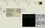
Hello,I would like to implement a VFD with PIC16F1937 and mainly IR21362 and Power MOSFET ,could you please help me to deal with those Codes,I made a 120degrees phase shift but the capabilities of making the frequency and amplitude adjustable remain difficult for me,please help,find the codes here below:
PHP:
#define NUMBER_OF_TABLE_ENTRIES_FOR_180_DEGREES 64
#define FACTOR_TO_GET_360_DEGREES

char i = 0;
double value_adc;

unsigned int sin_table[64] = {125,137,149,161,173,184,194,204,
                              213,222,229,235,240,245,248,249,
                              250,249,248,245,240,235,229,222,
                              213,204,194,184,173,161,149,137,
                              125,113,101,89,77,66,56,46,
                              37,28,21,15,10,5,2,1,
                              0,1,2,5,10,15,21,28,
                              37,46,56,66,77,89,101,113
                             };

unsigned int TBL_POINTER_NEW[3], TBL_POINTER_OLD[3], TBL_POINTER_SHIFT[3], SET_FREQ = 0;
unsigned int ADC_VAL = 0, PREV_ADC_VAL = 0;
char DUTY_CYCLE[3];
//Timer2
//Prescaler 1:1; Postscaler 1:2; TMR2 Preload = 249; Actual Interrupt Time : 100 us
//Place/Copy this part in declaration section

 /*

void InitTimer2() {
    T2CON = 0x0C;
    PR2 = 249;
    TMR2IE_bit = 1;
    INTCON = 0xC0;
}                        */

void interrupt()
                {
    if(TMR2IF_bit==1) {

        TBL_POINTER_NEW[0] = TBL_POINTER_OLD[0] + SET_FREQ;
        if (TBL_POINTER_NEW[0] < TBL_POINTER_OLD[0]) {
           CCP1CON.P1M1 = ~CCP1CON.P1M1;
        }
        TBL_POINTER_SHIFT[0] = TBL_POINTER_NEW[0] >> 10;
        DUTY_CYCLE[0] = TBL_POINTER_SHIFT[0]*value_adc;  //check this for multiplicity of value with read data from potentiometet
        CCPR1L = sin_table[DUTY_CYCLE[0]];
        TBL_POINTER_OLD[0] = TBL_POINTER_NEW[0];

       // Phase2
        TBL_POINTER_NEW[1] = TBL_POINTER_OLD[1] + SET_FREQ;
        if (TBL_POINTER_NEW[1] < TBL_POINTER_OLD[1]){
           CCP2CON.P2M1 = ~CCP2CON.P2M1;
        }
        TBL_POINTER_SHIFT[1] = TBL_POINTER_NEW[1] >> 10;
        DUTY_CYCLE[1] = TBL_POINTER_SHIFT[1]*value_adc;
        if((DUTY_CYCLE[1] + 42) < 64)DUTY_CYCLE[1] += 42;
        else DUTY_CYCLE[1] -= 22;
        CCPR2L = sin_table[DUTY_CYCLE[1]];
        TBL_POINTER_OLD[1] = TBL_POINTER_NEW[1];
        //Phase 3
         TBL_POINTER_NEW[2] = TBL_POINTER_OLD[2] + SET_FREQ;
        if (TBL_POINTER_NEW[2] < TBL_POINTER_OLD[2]) {
           CCP3CON.P3M1 = ~CCP3CON.P3M1;
        }
        TBL_POINTER_SHIFT[2] = TBL_POINTER_NEW[2] >> 10;
        DUTY_CYCLE[2] = TBL_POINTER_SHIFT[2]*value_adc;
        if((DUTY_CYCLE[2] + 21) < 64)DUTY_CYCLE[2] += 21;
        else DUTY_CYCLE[2] -= 43;
        CCPR3L = sin_table[DUTY_CYCLE[2]];
        TBL_POINTER_OLD[2] = TBL_POINTER_NEW[2];
        TMR2IF_bit = 0;
    }
}
     //Interrupt for ADC Value recording  ,reading the
     void interrupt_ADC()
          {

      if(ADIF_bit==1)
      {
      value_adc=ADRESH;
      //value_adc=ADRESL;
      ADIF_bit=0;
      }
           }

void main() {


    SET_FREQ=171;
    T2CON = 0x0C;
    PR2 = 249;
    TMR2IE_bit = 1;
    INTCON = 0xC0;

     Delay_ms(2);
     APFCON = 0x00;
     ADCON1 = 0X20;
     ADCON0=0X19;
     delay_us(20);
     ADCON0.GO=1;
     FVRCON = 0x00;
     ANSELA =0X3F;
     LATA=0X00;
     CM1CON0 = 0x00;
     CM2CON0 = 0x00;
     TRISA = 0x01;
     TRISB = 0xDF;
     TRISC = 0xF9;
     PORTB = 0x00;
     PORTC = 0x00;
     LATA = 0x00;
    //Initiailization ADC reading modules

        ADCON0.ADIF=0;
     //while(ADIF==0)

     ADCON0.ADIF=0;
     ADCON0.ADIE=1;
     PIE1.ADIE=1;
     INTCON.GIE=1;
     INTCON.PEIE=1;
     delay_us(20);
    // ADCON0.F2=1;


     //ADC_Init();
     //loop for cycles repeating


     for(i = 0; i < 3; i++)
            {
         TBL_POINTER_SHIFT[i] = 0;
         TBL_POINTER_NEW[i] = 0;
         TBL_POINTER_OLD[i] = 0;
         DUTY_CYCLE[i] = 0;
             }
     PWM1_Init(10000);
     PWM2_Init(10000);
     PWM3_Init(10000);

     PWM1_Set_Duty(0);
     PWM2_Set_Duty(0);
     PWM3_Set_Duty(0);

     PWM1_Start();
     PWM2_Start();
     PWM3_Start();
   // InitTimer2();
     while(1)
              {
              ADC_VAL=value_adc;
          }
     }