Continue to Site

Welcome to EDAboard.com

Welcome to our site! EDAboard.com is an international Electronics Discussion Forum focused on EDA software, circuits, schematics, books, theory, papers, asic, pld, 8051, DSP, Network, RF, Analog Design, PCB, Service Manuals... and a whole lot more! To participate you need to register. Registration is free. Click here to register now.

[MOVED] PIC16F877a first basic program.

Status
Not open for further replies.

amaant1

Newbie level 3
Joined
Jan 13, 2016
Messages
3
Helped
0
Reputation
0
Reaction score
0
Trophy points
1
Activity points
31
Hi, I made a program through MPlab IDE which is mention below;

Code C - [expand]
1
2
3
4
5
6
7
8
9
10
11
12
13
14
#include <htc.h>
#define _XTAL_FREQ 4000000
void main()
{
    TRISB=0x00;
    PORTB=0x00;
    while(1)
    {
        PORTB=0xFF;
        __delay_ms(100);
        PORTB=0x00;
        __delay_ms(100);
    }
}


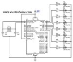
I'm using PIC16f877a and I used attached schematic as a reference. This circuit works perfectly on proteus which is a PIC simulation software but after transfering .hex file, not a single LED is blinking in my circuit. I couldn't find a problem. by the way I am supplying 5v through variable power supply which I made at home.
 

Attachments

  • Blinking-LED-using-PIC-Microcontroller-Circuit-Diagram.jpg
    Blinking-LED-using-PIC-Microcontroller-Circuit-Diagram.jpg
    439.6 KB · Views: 65
Last edited by a moderator:

A common error made with the "blinking LED" program is not configuring the oscillator, watchdog, etc. which Proteus tends to ignore. The 877 default for the oscillator is RC and you are using a crystal. What is the configuration command you are using?
 
Last edited:

I don't exactly know which configuration command you are asking but in MPlab the configuration which I set is;

  • OSC Oscillator HS
  • WDT Watchdog timer On
  • BODEN Brown out detect On
  • PUT Power up Timer Off
  • LVP Low voltage program enabled
  • CPD Data EE read protect Off
  • WRT Flash program write
  • CP Code protect Off
 

You defined Watchdog as ON, but there isn't in code any command to clear its timer.
 

I followed the pattern from the website. Do you have any suggestion for changes?
 

If your circuit is EXACTLY like the one pictured, how did you program the chip? As Easyrider83 noted, you need a pull-up on the MCLR line rather then hard-wired to 5V. The programmer needs to toggle MCLR to get the program into the chip.

Also, I would disable the watchdog timer and brown out.

I would also disable the "blink" part until everything else has been verified to work. Change both port B settings to 0xff to simply turn the LEDs on. Once you can get them to durn on, you'll know the oscillator is working and the configuration is correct. Then you can change one of them back to 0x00;

Another nit to pick, the schematic shows an 8 MHz crystal which would match your configuration setting for the oscillator (HS) but your code shows the clock at 4 MHz. Could the LEDs actually be turning on and off but the duty cycle is keeping you from seeing them? The "blink" disable above would confirm.
 
Last edited:

Status
Not open for further replies.

Similar threads

Part and Inventory Search

Welcome to EDABoard.com

Sponsor

Back
Top