Continue to Site

Welcome to EDAboard.com

Welcome to our site! EDAboard.com is an international Electronics Discussion Forum focused on EDA software, circuits, schematics, books, theory, papers, asic, pld, 8051, DSP, Network, RF, Analog Design, PCB, Service Manuals... and a whole lot more! To participate you need to register. Registration is free. Click here to register now.

Phase locked loop locking problem

Status
Not open for further replies.

hanikapa

Member level 4
Joined
Feb 6, 2015
Messages
71
Helped
0
Reputation
0
Reaction score
0
Trophy points
6
Activity points
510
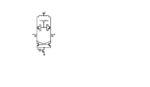
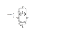
I have designed a PLL in cadence. The VCO structure is based on LC. the control voltage enters into lock range but unfortunately the structure cant get to phase locking. Does any body have any experience about this problem?
Thanks
 

Probably everyone that has used PLL's has had a problem with locking.
Need your circuit diagram to give a more detailed answer.
 

phase detectors filter must exceed frequency error of LC , which tend to be poor in % tolerance and large ppm drift /'C.

Use a crystal and counter divider but verify by increasing gain-bandwidth.
Use dual BW analog switch once locked.
 

The structure is as usual PLL circuits including PFD, Charge pump, passive filter, VCO and frequency devider. the vco frequency is 4GHZ and the frequency divider ratio is 128.
 

Well, so far it's unclear whether it enters the
and fails to lock, and passes on through to out-of-lock
on the other side, or oscillates about the lock-point.

Sometimes people add a "sweeper" that forces the PLL
to tavel through the pull-in range, just like analog startup
circuits are needed in voltage references. This addresses
a stuck-at-rail initial condition.

Is your loop amp maintaining proper (not flipping) phase
if railed one way or another? Might have a look at the
pieces and verify monotonicity etc.
 

The pll enters into frequency lock range and the control voltage become constant but there are oscillations on the control voltage that I think it is the cause that prevents the pll from phase locking. I did some test for none LC oscillators and there is not this problem but for LC oscillator the problem exists.
 

The pll enters into frequency lock range
and the control voltage become constant
but there are oscillations on the control voltage
I did some test for none LC oscillators
and there is not this problem
but for LC oscillator the problem exists.
Kvco is same between non LC oscillator and LC oscillator ?

I think LoopBW is too large or phase margin is lacking due to large Kvco of LC oscillator than non LC oscillator
 

yes Kvco is the same for both oscillators. kvco is about 400MHz for the VCO with 4GHz center frequency. The LC oscillator is controlled by applying control voltage to MOS varactors.
 

yes Kvco is the same for both oscillators.
Is it true ?
I think your Non-LC-Osc is Ring-Osc. Right?
If so, it is very difficult to make Kvco same between LC-OSC and Ring-Osc.

By the way, show me loop filter configuration.
 
Last edited:

yes my none LC VCO is ring VCO. Also I tried the loop with VCO from the cadence library and it could lock. But my problem is for my LC vco. The loop filter is second order. R=1KHz, C1=100Pf, C2= 20Pf. i also tried with other loop filter parameters but the result didnt change. I just did some tests on VCO itself. When I connect a dc voltage to varactor, no problem. But when i give this DC voltage to the gate of PMOS for example and then connect the drain of PMOS to varactors, I see there are the same oscillations on the varactor control similar to those that I had in pll. my VCO is a simple one consisting of two crosses NMOs, One inductor in parallel with nmos varactors. for varactors the control voltage is given to their drain and source.
 

Also I tried the loop with VCO from the cadence library and it could lock.
I can't understand what you want to mean.
Describe in detail.

But when i give this DC voltage to the gate of PMOS for example
and then connect the drain of PMOS to varactors,
I can't understand what you want to mean.
Describe in detail.

my VCO is a simple one consisting of two crosses NMOs,
One inductor in parallel with nmos varactors.
for varactors the control voltage is given to their drain and source.
It seems your problem is in VCO itself not due to PLL.

Show me circuit topology of your VCO.
 

Based on my VCO structure I have 10 Varactors in parallel.
 

Attachments

  • vco.png
    vco.png
    26.1 KB · Views: 109

But when i give this DC voltage to the gate of PMOS for example and then connect the drain of PMOS to varactors, I see there are the same oscillations on the varactor control similar to those that I had in pll.
I can't find out PMOS you refered.
 

i attached the figure with pmos
 

Attachments

  • vco.png
    vco.png
    30.4 KB · Views: 113

Attach decoupling capacitor, e.g. 100pF to both Vcc and Vdd node.

And DC voltages are different between VCONTROL(=Gate of PMOS) and Varactor node.

PMOS circuit is common source amplifier(Inverted Amplifier).
So you have to change polarity of PFD.
 
Last edited:
Unfortunately, the problem didnt solve and still there are oscillations on varactor node
 

yes, I mean VCO alone. the body is connected to vcc which is the highest voltage in circuit.
 

If you include PMOS common source amplifier, loop-characteristics will be different from loop based on ring-osc.
So you have to design loop filter including PMOS common source amplifier.

And output impedance of PMOS amplifier is relative high.
This is a reason why you observe oscillation at varactor node for VCO alone.
So you have to put capacitor at varactor node, e.g. 10pF.
So Total loop filter including PMOS Amplifier is inverted 3rd order.
There you have to design loop filter including PMOS common source amplifier and this 10pF.
 
Last edited:
Thank you very much for your helpful comments. I will try this. I think this will work :)
 

Status
Not open for further replies.

Similar threads

Part and Inventory Search

Welcome to EDABoard.com

Sponsor

Back
Top