Continue to Site

Welcome to EDAboard.com

Welcome to our site! EDAboard.com is an international Electronics Discussion Forum focused on EDA software, circuits, schematics, books, theory, papers, asic, pld, 8051, DSP, Network, RF, Analog Design, PCB, Service Manuals... and a whole lot more! To participate you need to register. Registration is free. Click here to register now.

100G PLL Design in Cadence

astroshey

Newbie level 6
Newbie level 6
Joined
Nov 21, 2021
Messages
12
Helped
0
Reputation
0
Reaction score
0
Trophy points
1
Activity points
106
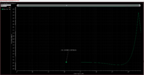
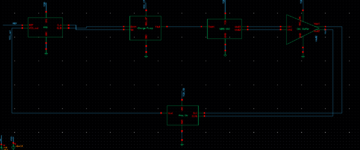
I am running into a very weird issue when calculating the phase noise of my PLL in cadence. The bandwidth of my filter is too large, even though I am calculating the loop filter parameters (Cp Rp C2) using zeta and natural frequency formulas from Razavi's book. Please see the attached image. Can someone suggest any ideas to resolve or troubleshoot this issue. Also, attaching the block diagram of my PLL for reference. Thank you for any help!!
 

Attachments

  • Capture.PNG
    Capture.PNG
    104.5 KB · Views: 28
  • Capture1.PNG
    Capture1.PNG
    21.1 KB · Views: 30
Solution
There can be PN contributors which are not removed by the filter.

A method of substituting ideal blocks for various sections, or conversely substituting in transistor-level blocks one by one to a full-up behavioral lineup, is how I like to poke at misbehaviors.

dick_freebird

Advanced Member level 7
Joined
Mar 4, 2008
Messages
8,244
Helped
2,293
Reputation
4,596
Reaction score
2,334
Trophy points
1,393
Location
USA
Activity points
65,957
There can be PN contributors which are not removed by the filter.

A method of substituting ideal blocks for various sections, or conversely substituting in transistor-level blocks one by one to a full-up behavioral lineup, is how I like to poke at misbehaviors.
 
Solution

astroshey

Newbie level 6
Newbie level 6
Joined
Nov 21, 2021
Messages
12
Helped
0
Reputation
0
Reaction score
0
Trophy points
1
Activity points
106
I found the ideal freq divider block in rflib. I need to assign the parameters in the block now. My input frequency is around 100GHz, and I need an output frequency of 100MHz - so I need a divide ratio of 1000. I have attached a screenshot of the parameters I have assigned. These parameters are not correct since I am getting a 0 output out of the freq div block (see attached waveform). Please let me know how I should assign the parameters in the freq divider given my frequency requirements. I appreciate any help! Green is the output of my VCO and purple is the output of freq divider.
 

Attachments

  • 1.PNG
    1.PNG
    49.8 KB · Views: 20
  • 2.PNG
    2.PNG
    54.7 KB · Views: 17
Last edited:

LaTeX Commands Quick-Menu:

Part and Inventory Search

Welcome to EDABoard.com

Sponsor

Top