Continue to Site

Welcome to EDAboard.com

Welcome to our site! EDAboard.com is an international Electronics Discussion Forum focused on EDA software, circuits, schematics, books, theory, papers, asic, pld, 8051, DSP, Network, RF, Analog Design, PCB, Service Manuals... and a whole lot more! To participate you need to register. Registration is free. Click here to register now.

Transistor third overtone oscillation circuit

Status
Not open for further replies.

cippy

Newbie level 5
Joined
Aug 12, 2015
Messages
10
Helped
0
Reputation
0
Reaction score
0
Trophy points
1
Activity points
69
Hi all

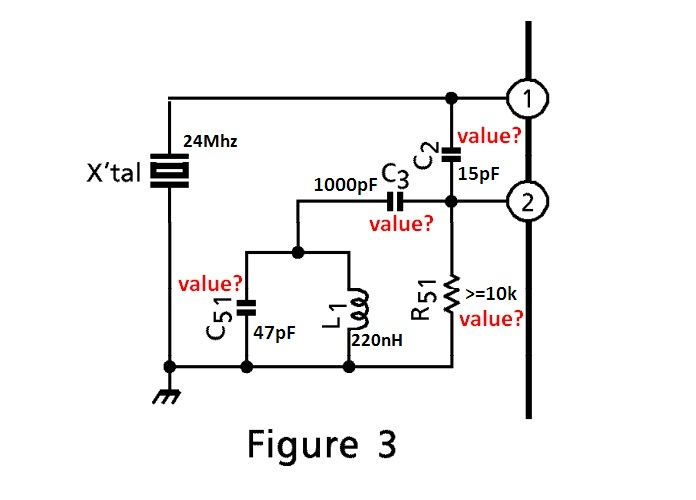
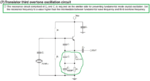
I would like someone to explain to me how I can make the circuit below work on the third harmonic.
What values do I need to C3 and C4, and how is it calculated?

desired frequency = 72 Mhz
Xtal = 24 Mhz
L2 = 220 nH

Thank in advance
Robert
 

Attachments

  • third overtone.png
    third overtone.png
    241.7 KB · Views: 393
Last edited:

When calculating an LC resonant loop, it is common to make the L value between 1,000 and 1 million times the C value. This is suitable for voltage swings of a few V and Ampere flow of a few mA.

It can also be a question how many capacitors are included in the resonant loop. Perhaps it is only C3. Therefore suitable values might be in the area of 220 nH and 22 pF, to resonate at 72 MHz.
 

basically, you need some L-C circuit that stops it from oscillating at the fundamental frequency, while letting it run at the 3rd harmonic.
 

Contrary to the schematic shown, I used a similar circuit with the output taken from a collector LC circuit tuned to n-th harmonic. The emitter circuit was similar to the shown one but I used a capacitor trimmer to optimize the selected harmonic output.
My harmonic oscillator used the same frequency combination, 24 MHz quartz and 72 MHz output. Adjusting the emitter circuit was important as many quartz crystals are different, one-by-one. Also transistor operating point had to be fine-tuned fo the best result.
 

Here is an other simple option:


Please, I want a math formula, a calculation method for correct choosing , C3, C4 capacitive divider, for this circuit,to oscillate the third harmonic?
desired frequency = 72 Mhz
Xtal = 24 Mhz
L2 = 220 nH

- - - Updated - - -

I know the theory, but do not know how to calculate
Inductive at fundamental frequency and capacitive on third harmonic ...
 

C4 is not a part of the capacitive divider. It is just an AC bypass capacitor.

C2 and (C3 || L2) forms the capacitive divider.

At first you need to choose/calculate the capacitance of the two elements in the capacitive divider for 72Mhz. Suppose you have chosen C2=15pF and (C3 || L2)=30pF. From post #2 you know that L2 resonate with 22pF at 72Mhz. So to get 30pF from (C3 || L2) at 72Mhz, C3 must be 22pF+30pF=52pF.
 
  • Like
Reactions: cippy

    V

    Points: 2
    Helpful Answer Positive Rating

    cippy

    Points: 2
    Helpful Answer Positive Rating
Hi ahsan_i_h

Please help me and with this schematics from TA31136 datasheet..
I want a formula, the calculation method for this circuit, 3rd overtone mode(overtone oscillation)
72 Mhz desired frequency
X-tal = 24 Mhz
L1 = 220 nH
C51, C3, C2, R51 value?

https://www.discriminator.nl/ic/ta31136.pdf page 4

Thank you very much
Best Regards,
 

Attachments

  • TA31136 ic receiver.png
    TA31136 ic receiver.png
    98.5 KB · Views: 226
  • TA31136 ic receiver 1.png
    TA31136 ic receiver 1.png
    78.1 KB · Views: 134
Last edited:

According to the Spec, Pin 2 has 120uA current sink and Pin2 should be 1.33V thus equivalent to R5 being in the range of 10K. Since this filter is a parallel resonant circuit R5 determines the gain from the Q=R5/X(f), where X(f) is the inductor reactance at resonance. If we assume the overtone is 15 dB down, we need a Q of at least 20 or more. to force resonance at the overtone. Some resonators will give the overtone ratio.

Thus now you can determine L, then the equivalent C in parallel with L at resonance. Then Adjust R5 for the Q gain or desired level out.

A better method at times is to use a series LC to trap the fundamental for better rejection but then here they use a CMOS inverter with gain rather than a high Q common collector with unity gain.
 

To calculate the capacitance of two capacitors in the capacitive divider of a crystal controlled colpitts oscillator, you need several parameters related with amplifier and crystal. See the equations in the picture below.


Reference: https://www.qsl.net/dk1ag/ukw1979_e.pdf (Page 6,7)
[ Design of crystal oscillator circuits - by B.Neublg ]

Fortunately you already have those capacitance values (upper capacitor=39pF,lower capacitor=56pF) for 21.25MHz on page 8 & 14 of the TA31136 datasheet. But you need capacitance values for 72MHz.

For 72MHz, the upper capacitor should be near 39pF*(21.25/72)=11.5pF,lets take it 15pF. And the lower capacitor should be near 56pF*(21.25/72)=16.5pF,lets take it 22pF.


So in the above picture,
C2=15pF.
(C51||L1)=22pF @72MHz, so C51=22pF+22pF=44pF,lets take it 47pF.(Follow post#7)
C3 is for DC block/AC bypass, So it must have very low reactance at 24MHz. Lets take C3=1000pF.
At 72MHz, if signal level at pin 2 is insufficient (below 95dBuV=56mV) then you need to put R51. You may find the value of R51 using a variable resistor experimentally. In post#9, SunnySkyguy has already suggested a range for it.
 

Hi ahsan_i_h

Thank you very much for reply.

This calculation is for this transistor oscillator?

To calculate the capacitance of two capacitors in the capacitive divider of a crystal controlled colpitts oscillator, you need several parameters related with amplifier and crystal. See the equations in the picture below.


Reference:
https://www.qsl.net/dk1ag/ukw1979_e.pdf

(Page 6,7)
[ Design of crystal oscillator circuits - by B.Neublg ]

Fortunately you already have those capacitance values (upper capacitor=39pF, lower capacitor=56pF) for 21.25MHz on page 8 & 14 of the TA31136 datasheet. But you need capacitance values for 72MHz.

For 72MHz, the upper capacitor should be near 39pF*(21.25/72)=11.5pF,lets take it 15pF. And the lower capacitor should be near 56pF*(21.25/72)=16.5pF,lets take it 22pF.
 

Attachments

  • third overtone.png
    third overtone.png
    276.2 KB · Views: 264
  • ta 31136.png
    ta 31136.png
    66.7 KB · Views: 108
Last edited by a moderator:

Hi cippy, marked area in the right picture (a snapshot of post#10) is for TA31136. See the picture below..


All the oscillator pictures you already have uploaded are variants of colpitts oscillator. So at first, you need to understand designing colpitts oscillator. Therefore, at the begining of post#10 some necessary formulas (for calculation of capacitive divider) are given. See the picture below..


The above formulas are difficult to use due to the lack of information of amplifier and crystal. But without the information of amplifier and crystal, and assuming several terms as frequency independent, we can obtain results for one frequency if we have results for another frequency. We have results for 21.25MHz so we have found results for 72MHz. See the picture below..


You may ask how a complex oscillator circuit (Third overtone oscillator circuit of T31136) will behave as a simple colpitts oscillator circuit.

At third overtone the LC network made by L1 and C51 will behave as capacitive, as a result the circuit will look like a colpitts oscillator and it will oscillate as a colpitts oscillator. On the other hand, at fundamental frequency the LC network made by L1 and C51 will behave as inductive, as a result the circuit will not look like a colpitts oscillator, and due to phase related problem in feedback network it will not oscillate. Note that as the reactance of C3 is too low (because it is a DC block capacitor), neglect the effect of C3 for this explanation.

Now imagine that the third overtone oscillator circuit of TA31136 is oscillating at the third overtone (72MHz). So we will imagine the parallel combinanion of L1 and C51 as a single capacitor. Let its name is Cx. Now neglecting C3, if we draw the picture, it will look like the picture below..


Now what should be the value of C2 and Cx? We already have calculated these in the 9th and 10th line of post#10. These are C2=15pF and Cx=22pF.

To calculate C51, first we need to find the capacitance value which resonates with L1(220nH) at 72MHz using the formula f=1/(2*pi*sqrt(LC)). The capacitance is
found 22pF. So, at 72MHz susceptance of this 22pF will be cancelled by the susceptance of L1(220nH). So to get additional 22pf for Cx, C51 should be 22pF+22pF=44pF.

If you test (C51||L1) with found values, you will find that it is capacitive at 72MHz and inductive at 24MHz. If the value of L1 was not given, then it would be relatively harder to find the values of both L1 and C51.
 

Hi ahsan_i_h

Thank you very very much for reply.

I would like to test excel spreadsheet, you tell me if calculated(work) correctly?
Let's look at the chart and that change
 

Attachments

  • overtone calc.zip
    47.4 KB · Views: 91

Hi cippy,
Sorry for late reply.

The excel spreadsheet seems ok. The circuit on the first sheet (calcul) is similar to the circuit of post#1. The capacitor (C1) parallel to the resistor (R2) is DC block / AC bypass capacitor. So its value should be high enough to neglect its effect down to 24 MHz. On the second sheet (tabele_ptr_grafice), you have calculated the impedance of the combined circuit at various frequency with two sets of data. In first set you used C1=1000pF and in second set you used C1=9.8pF which is too low, as a result you see the curve (faza_calculata) on the first sheet is too narrow.

It is difficult to understand the terms Fserie and Fderiv on the first sheet. What are these ? Also in the post#1 and post#8 you mentioned the inductance 220nH. How this value is chosen ? If you do a comprehensive calculation (solving two equations), you can find inductance and capacitance of the tank circuit at the same time.
 

Here is a simulation using a model of 3rd OT crystal at 72 MHz to illustrate the modes of operation.

In the first case, you can see the dominant 72 MHz tone.

If we short out the 24 MHz trap, then the crystal can still oscillate at the fundamental but at a lower amplutude.
 

Attachments

  • 72M_3OT_xtal.png
    72M_3OT_xtal.png
    59.5 KB · Views: 139

Status
Not open for further replies.

Part and Inventory Search

Welcome to EDABoard.com

Sponsor

Back
Top