Continue to Site

Welcome to EDAboard.com

Welcome to our site! EDAboard.com is an international Electronics Discussion Forum focused on EDA software, circuits, schematics, books, theory, papers, asic, pld, 8051, DSP, Network, RF, Analog Design, PCB, Service Manuals... and a whole lot more! To participate you need to register. Registration is free. Click here to register now.

A current detect circuit

Status
Not open for further replies.

NextEngine

Newbie level 4
Joined
Sep 26, 2014
Messages
7
Helped
0
Reputation
0
Reaction score
0
Trophy points
1
Activity points
60


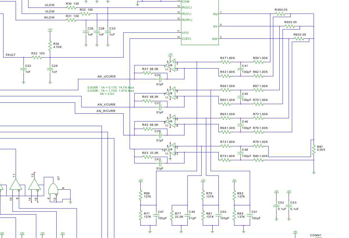
Hello, the picture above is an excerpt from a brushless DC motor controller schematic. The whole schematic is included in the attachment.
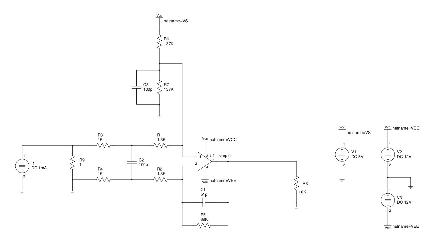
I have relayout the parts so that they look much clear, just as shown below.


The only thing I know is that this circuit is used to detect the current through the resistor R9. Instead of measuring the current directly, the circuit measures the voltage across R9, uses the resistors capacitors and opamp to process the voltage and finally put it into the AD port of the microchip.

I want to know how these resistors, capacitors and opamp work, what's the purpose of these parts? Can someone analyze this circuit?
 

Attachments

  • bldc-sch.pdf
    72.7 KB · Views: 50

U1 output = 68/2.8 times the volt drop across R9 plus the offset of 1/2 Vs. the capacitor just is a low pass filter working with R3, C1, provides feedback at high frequencies, because of its low value it will be used to offset phase shifts within the op-amp and also provides a HF roll off function.
Frank
 

Hi,

as you said, the whole circuit is a current measurement circuit.
I describe according picture2.

R1 is the shunt. proportional to the current there is a voltage drop. With 1 Ohms there is 1mV per 1mA.
C1, C2, C3 are for high frequency (switching frequency) suppression. you will measure only the motor winding current for rotating frequency (fundamental frequency)
U1 with R1...R7 build a differential amplifier with DC gain = 24.3 (now every mA gives 24.3mV)
R6, R7 additionally is to generate a DC offset in output voltage of VCC/2. (because of loosing precision, i personally don´t like to use VCC as a REF. I´d rather use ADC_REF/2)
(for symmetry C3 and C1 should be the same value. I can´t tell why they are different)

R3, R4 and C2 form a low pass filter with 800kHz (just not to overdrive the OPAMP input stage)
C1 and R5 (R6, R7 and C3) form a low pass with 46kHz to suppress switching frequency. (seems to be very high switching frequency. I guess 300 ... 500kHz)

R8 has no meaning here.

Klaus
 

........................................
The only thing I know is that this circuit is used to detect the current through the resistor R9. Instead of measuring the current directly, the circuit measures the voltage across R9,
...................................
How would you measure the current "directly"? The usual way to measure current is to measure the voltage drop across a small (shunt) resistor in series with the current. There are ways to measure the current by detecting the magnetic field around the wire, such as with a Hall effect device, but that technique is not as commonly used.
 

Hi,

with a Hall effect device, but that technique is not as commonly used

in high current / high voltage applications they are commonly used.


In many photovoltaic inverters, motor control and industry applicatins.


Klaus
 

in high current / high voltage applications they are commonly used.

In many photovoltaic inverters, motor control and industry applicatins.
Quite true. I didn't intend to imply that they were seldom used, just not as common as the resistive shunt technique.
 

Status
Not open for further replies.

Part and Inventory Search

Welcome to EDABoard.com

Sponsor

Back
Top