NextEngine
Newbie level 4

- Joined
- Sep 26, 2014
- Messages
- 7
- Helped
- 0
- Reputation
- 0
- Reaction score
- 0
- Trophy points
- 1
- Activity points
- 60

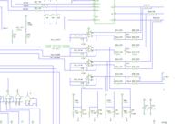
Hello, the picture above is an excerpt from a brushless DC motor controller schematic. The whole schematic is included in the attachment.
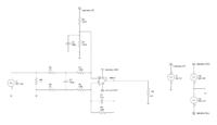
I have relayout the parts so that they look much clear, just as shown below.

The only thing I know is that this circuit is used to detect the current through the resistor R9. Instead of measuring the current directly, the circuit measures the voltage across R9, uses the resistors capacitors and opamp to process the voltage and finally put it into the AD port of the microchip.
I want to know how these resistors, capacitors and opamp work, what's the purpose of these parts? Can someone analyze this circuit?

