ElecDesigner
Member level 5
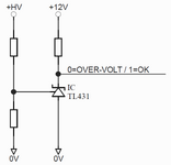
In the past I have used a 431 (shunt ref/reg) to detect over-voltage (or sometimes under-voltage) conditions on a HV rail. I would normally have a LV rail in addition that has circuitry to "action" the overvoltage condition.
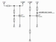
In the absence of a negative equivalent of the 431 the circuit becomes more complex (I assume) if the HV is negative. This is because the reference voltage is referenced to the negative terminal so is the circuit is flipped the precision of the circuit is governed by the accuracy of the 12V rail. I have come up with a "fix" for that using two references but I have this nagging doubt about if I'm missing something and there is an easier way of doing it.
I have shown the 12V is positive here but that could easily be -12V (generated by an isolated PSU).
Of course I could use the positive circuit with the circuit floating at -HV potential but I don't want to do that.