matin-kh
Member level 3
Hello,
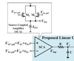
I have an amplifier which its output is shown below:

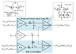
I use a peak detector to detect the amplitude of the output of amplifier which its circuit is like this:

I have a problem when I connect the output of amplifier to the peak detector the output of amplifier would be like this:

as you see the amplitude of out- is higher than out+ and it damage the output of peak detector i can't understand the reason with sin source the power detector don't act like this and every thing is ok, do you know what is the problem?
I have an amplifier which its output is shown below:

I use a peak detector to detect the amplitude of the output of amplifier which its circuit is like this:

I have a problem when I connect the output of amplifier to the peak detector the output of amplifier would be like this:

as you see the amplitude of out- is higher than out+ and it damage the output of peak detector i can't understand the reason with sin source the power detector don't act like this and every thing is ok, do you know what is the problem?

