michael 1978
Advanced Member level 4
please can you help, explain me in easy way this circuit
https://obrazki.elektroda.pl/2237673700_1387888073.jpg
normal must be
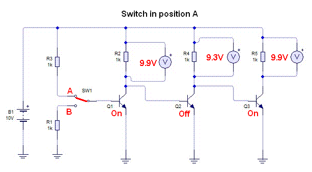
swith in position A
q1 on
q2 off
q3 on
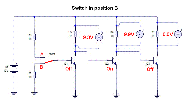
switch in position B
q1 off
q2 on
q3 off
https://obrazki.elektroda.pl/2237673700_1387888073.jpg
normal must be
swith in position A
q1 on
q2 off
q3 on
switch in position B
q1 off
q2 on
q3 off