Continue to Site

Welcome to EDAboard.com

Welcome to our site! EDAboard.com is an international Electronics Discussion Forum focused on EDA software, circuits, schematics, books, theory, papers, asic, pld, 8051, DSP, Network, RF, Analog Design, PCB, Service Manuals... and a whole lot more! To participate you need to register. Registration is free. Click here to register now.

How to make a working super pulsed laser module or device?

Status
Not open for further replies.
Keith:)
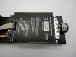
, can i ask what did you mean by saying "a pre built board like that"?

Do you mean i can buy a board that contains everything i need and i just need to plug the laser diode and connect the 5V adapter to the board and power my laser?

I found sth like that, i attached. But it's quite expensive: 960 Euro!!!

Can you recommend me a cheaper one?:)
 

Attachments

  • VFM 1,5-25 10100368 mit OSRAM PL TB450 Foto 2.JPG
    VFM 1,5-25 10100368 mit OSRAM PL TB450 Foto 2.JPG
    335.2 KB · Views: 92

What I meant was, using the ETX-10A will be a lot easier than having to do the whole design yourself. In particular, the difficult parts are done for you - high current drive and PCB layout. While you have to add a few parts (pulse generator and a few capacitors) it is fairly straightforward.

Keith
 
Yeah I see.

But it still:grin: feels a little difficult for me because i've never done things like this before and never studied electronics..

But thanks to you I'm sure i will succeed eventually.
 

What I meant was, using the ETX-10A will be a lot easier than having to do the whole design yourself. In particular, the difficult parts are done for you - high current drive and PCB layout. While you have to add a few parts (pulse generator and a few capacitors) it is fairly straightforward.

Keith

Sorry, for bumping an old thread, but I think this will be of help to future readers, and it's an excellent resource thanks to keith.

$150 is not unreasonable if you only need 1, but if your project requires multiple drivers, then it gets a bit expensive.

Here is a design from **broken link removed** built specifically for the SPL PL90 25W pulsed laser diode.

It's Creative Commons licensed, so I will paste the relevant sections.

OSLRF-LD.png

OSLRF-PS.png

Code:
VIN is 12V (10-18V)

IC10      - L78L08, 8V, linear regulator
IC11      - L78L33, 3.3V, linear regulator
IC17      - MIC44F18, MOSFET driver
Q1        - BSP318S, avalanche SIPMOSFET
C18, C19  - 10uF, 16V, X7R
R21       - 100R, 1%
R22       - 27R, 1%
C36, C37  - 2 x 22nF, 50V, COG
C38       - 10uF, 16V, X7R
C39       - 0.1uF, 25V
D2        - 1N5819, diode
LAS1      - SPL_PL90, 25W laser

Now if I may ask an exceptionally stupid question: All the (other) pulsed laser diode driver circuits I have seen, and even the specs on the ETX-10A say things like: "Pulse Repetition Rate (contin. Ipk=40A,Vdis=115V)"

How can a voltage of 115V be used with a laser diode like the SPL LL90, which has a specified maximum voltage of 5V, and not fry the diode to next thursday?

I assume I am missing some basic law of electronics, but it seems worth checking before I start blowing up $40 diodes.
 

Inductance is often a limiting factor so high voltages are used to reduce the rise time with a fixed inductance. 5nH is typical of the package inductances. If you want a very fast rise time/short pulse, the only way is with a high voltage if you are stuck with such an inductance. The high voltage doesn't reach the laser - but it does exist on the other side of the stray inductance. Just start with a low voltage and increase it while monitoring current. It is the current that will kill the laser. It can be difficult to measure the current so the rate of discharge of the storage capacitor can be a good alternative.

Keith.
 

Where does the high voltage go?

Would it be too heinous a simplification to say that:

oopfvosram.png

As the laser diode attempts to draw an infinite amount of current the voltage increases, but the capacitor is emptied before current (and voltage) can exceed specified limits?

Or is that just total nonsense.

I'll be using a test load to being with (0.1ohm of resistance) so I should be able to infer current from there, using my DSO, no?
 

I think maybe I understand the driver example in the SPL PL90 datasheet a little better now.

splpldriver.jpg

I couldn't fathom all the inductance coils, especially as it states "it is very important to minimize the inductance of the circuit."

Perhaps L1-L5 are there to remind the engineer that inductance is implied, and should be minimized?

Sorry for the dead-head questions. I usually try and stick to microcontrollers.
 

Perhaps L1-L5 are there to remind the engineer that inductance is implied, and should be minimized?
Obviously. It looks like a simulation circuit, trying to describe the real hardware behaviour as close as possible. The challenge is to identify the parasitic inductance values.
 

You need two things - a power supply and something to generate the pulses. Usually the pulse width on laser drivers is determined by the capacitor value, laser current and voltage. So, you don't need to generate a really short pulse. A 74AHC123 dual monostable should do fine.

Keith

The Absolute max specs for this Laser are;
35A @150ns but the performance is rated at 100ns.

Keep in mind Excessive light levels, can damage the tiny end mirrors of the lasing crystal, so it is not the thermal capacity of the diode.

Current monitoring is essential as the forward voltage drop will have a wide tolerance due to ESR variations and as well as smaller thermal effects on the forward voltage (NTC)

Something with 100ns +/-10ns pulse width will likely need a rise/fall time from 1 to 3ns which is equivalent 100~300MHz bandwidth. THe tail time is more critical as one cannot simply use an open drain driver or precharge a capacitor and dump it. ( due to wide variations in ESR and Vf of laser) due to slow turn-off or decay time. This usually implies a source follower, common gate or push-pull driver.

( so a 74HC123 won't cut it)

Surface mount devices should only be considered and very short path <1cm and small area loop in the current pulse. Otherwise ringing will be excessive and pulse width can burn out the reflector.

You will want to beg, borrow or steal a Le Croy scope to confirm the design does not burn out laser diodes and brush up on spark measurements with no ringing. If you can't measure a spark current without ringing from stray inductance, you don't have a chance in designing measuring a laser diode pulse.

Avalanche transistor suggested previously sounds like a good choice but overall design & board layout is critical.

If therapeutic treatment is the goal, I suggest any good accupuncture Dr. will have these tools. MY accupuncture Doctor is Armenian from Tehran has a handheld one worth >$3k and the mini LCD/ keypad has a password for safety. But you need to know acupuncture to use it like a needle>

I can also swear by the effective treatments of long wave Infrared Therapy for many similar injuries which has a deeper skin effect than sub 1 micron IR. FIR or far IR in therapeutic band is 5~25um. I bought a TDP lamp from Dr. Li for over $500 30 yrs ago in San Francisco and it still works on all kinds of serious ailments.( Probably cheaper now) It works using short IR back heater to convert phosphor minerals on ceramic disk to long IR. I found a Korean Dr of Acc. who had a clay oven for therapy that was only $20/hr It used similar minerals to convert short IR heaters to longwave IR ( Germanium clay I believe).

So if this therapeutic tool is really important, do it right or seek alternatives and don't waste time.
2013-12-11 17.06.49.jpg

- - - Updated - - -

This pulse might seem perfect for driving the 200W Laser Diode, but you will ROTFLOL when you see what I used to create this signal....

5 legged core.png

20kV applied with partial discharge in charged magnetic particles with this 5MVA core in oil in its tank. ( It weighs a few tons)
This was only in 50 Ohm load and not 50 milliohm like the Laser diode.

.... which reminds me.. if you want an easier way to create this pulse cheap.. use a microwave oven transformer (MOT) from a scrap oven and strip the secondary or replace it with 1 or more turns of 12 guage wire and monitor with high quality microwave coax on a 50 Ohm scope with impedance matching at source and sense current in laser and light output both . Think how a soldering gun works with 1 turn of copper including the tip... except you charge up the transformer with low current 100 voltage DC then open with a contactor HV relay and stored energy is transferred to the secondary like a flyback transformer, the primary arc is suppressed and an avalanche transistor-like speed pulse is created at low voltage capable of high current limited by another simple cct. OMRON 10A SPDT relays can oscillate at around 1kHz too with the coil interrupted by the NC contacts creating the avalanche arc , but lifetime on contacts will be shortened... but cheap........ I may just make one of these using tungsten spark plug gap to save relay contacts.
 

Basically, you need:
laser diode (LD)
collimation optics
current regulator (aka driver)
power supply
heatsink
something to house all the electronics (project box is ok for a first build)

then you can add other optional things:
safety switch
LED for power indication
cooling fan
etc...

These are the tools which are used to build a laser device.
soldering iron
solder
DMM (digital multi meter, even the cheapest works fine)
some wires (the more flexible the better)
small pliers

other useful tools:
tweezers
vice
3rd hand
 

The 74AHC123 I mentioned was to drive the ETX-10A not a laser so I am sure is perfectly adequate.

Keith
 

Status
Not open for further replies.

Part and Inventory Search

Welcome to EDABoard.com

Sponsor

Back
Top