Continue to Site

Welcome to EDAboard.com

Welcome to our site! EDAboard.com is an international Electronics Discussion Forum focused on EDA software, circuits, schematics, books, theory, papers, asic, pld, 8051, DSP, Network, RF, Analog Design, PCB, Service Manuals... and a whole lot more! To participate you need to register. Registration is free. Click here to register now.

Help need for drawing IIP3 and P1dB using AWR MICROWAVE OFFICE.

Status
Not open for further replies.
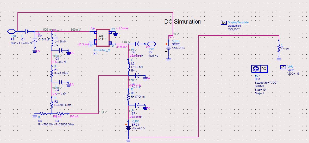
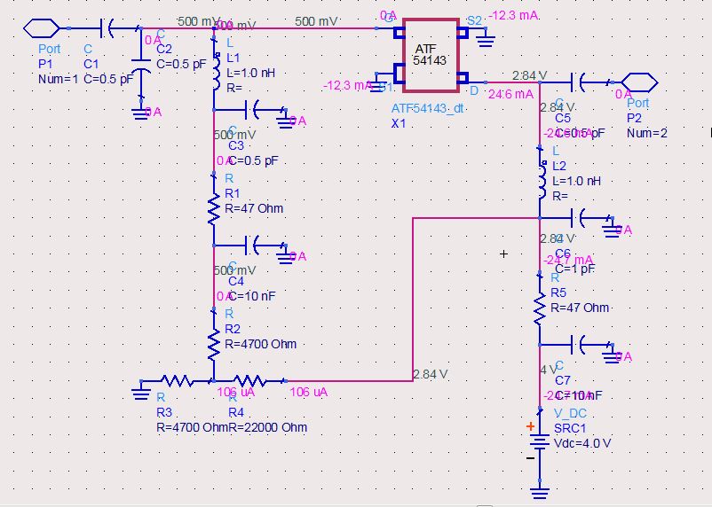
OK I gave up simulating this schematic.

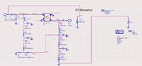
I started from beginning and used ATF 54143 application notes. I will change step by step. First i need DC simulation according to#22.


Why do you have the resistor connected from the ground pin of DC source #1 to ground? I does nothing at all. Also DC source #2 it AC coupled via C1 so it also will have no effect on the circuit. Double-check what you are doing here. This current circuit make no sense.
 
Thank you sir,

I did them to make a DC simulation. When i delete wrong connection i got correct results i think:


After this i want to simulate s-parameters. But it gives warning. What can i do?

"Either dc analysis was not performed in the last analysis of the design or dc data of Swept analysis cannot be back-annotated at this time"

warning.JPG
 
Last edited:

Dear husamsdu,
I am surprised, why you are using my post to clear your doubts. Please you can post your own doubt posting and get answer. This is not good way for getting answer from my own postings. You can post new thread and get answer.
 

Dear btv_murthy,

I just want to keep forum clear. I thought that if i post new thread it will be unnecessarily. Also i waited your helps coz you studied designing lna before.

Whatever i am sorry and i will post a new thread.

Dear husamsdu,
I am surprised, why you are using my post to clear your doubts. Please you can post your own doubt posting and get answer. This is not good way for getting answer from my own postings. You can post new thread and get answer.
 

This is part of the normal operation of Harmonic Balance simulation. The simulator will automatically adjust the power level as required to achieve convergence. It may be possible to avoid this by adding extra points to the power sweep. Try Start=-50 Stop=-10 Step=5 for Course Sweep Plan and Start=-9 Stop=10 Step=1 for Fine Sweep Plan.
RealAEL Sir,
For my application, I wanted to run Sweep Plan Course to Start =-50 stop= 20 step =5 and Sweep Plan Fine to start = -9 stop =10 step =1. I wanted to get the Sweep Plan course from -50 to +20 . But When I press the Simulation button, it starts to sweep from -50 to -9 . Afterwards -9, it will become too slow, it will take lot of time go ahead to sweep. I need from -50 to 20. How to make sweep plan course to sweep it faster to avoid more time consuming.

What is the difference between Sweep Plan course and Sweep Plan fine and what is the significance of sweep plan fine?
 

Attachments

  • Sweep_Plan_Fine and Sweep_Plan_Course.jpg
    Sweep_Plan_Fine and Sweep_Plan_Course.jpg
    424.2 KB · Views: 86
  • Simulation_Run.jpg
    Simulation_Run.jpg
    254.2 KB · Views: 76
Last edited:
When you increase the input power to a circuit any non-linear devices will become more and more saturated and this will always increase simulation time. If the simulation does not converge on a solution as expected then ADS will take some automated steps top attempt to resolve the non-convergence condition but this will be a direct cause of the increased total simulation time.

There are some steps that you can consider to Reduce Simulation Time but often these will result in reduced accuracy. The easy things to change are the number of frequencies, number of harmonics and the power level but these cannot be reduce too far for 2 tone simulation. You could also place the Options controller and increase the relative and absolute current and voltage tolerances. This will certainly reduce simulation time but will also reduce the accuracy. Simularly decreasing these tolerance values will increase the accuracy but will slow the simulation down. You need to find values that provide the best results in the optimum time. It is always a trade-off between speed and accuracy.
 
RealAEL Sir,
Now I reduced the step to -50 to +5 , and also introduced "OPTIONS". Also I set the OPTIONS, even though I set introduced options and I am getting the "convergence" problem. How to avoid the convergence problem.


Your numbers make no sense. V_AbsTol of 15 is way too high. The default RelTols are 1E-6 and V_AbsTol and I_AbsTol are 1E-6 and 1E-12 respectively. You would be better off experimenting by clearing those values and using the preset values for Relaxed or Intermediate Convergence Check (and allow for the reduced accuracy). See the Help Page for the Options Controller for more details. See further down the same page for explanation for Preventing Convergence Problems.

Also your Course and Fine sweeps overlap. You may as well stop the Course sweep at -10 and let the Fine sweep do the rest to +10.

Also it looks from your previous post that you are getting errors about unconnected nodes (with only one device attached) and nodes with no DC path to ground. Fix those warning and convergence will likely improve.
 
Also it looks from your previous post that you are getting errors about unconnected nodes (with only one device attached) and nodes with no DC path to ground.
RealAEL Sir,
What is this error unconnected nodes(with only one device attached) and nodes with no DC path to ground. I didn't understand these two errors, how I have to understand these errors and what I have to do for removing these errors
 

These errors mean exactly what they say.

You have some connections with only one symbol pin attached. Like a wire with a component at one end but not the other. To fix this make sure everything is correctly connected.

Also there are some nodes that have no connectivity to ground. An example would be two capacitors connected in series. The middle connection has no DC path to ground. Avoid that type of connection.

Both mean that there is something wrong with the circuit rather than something that can be fixed with simulation set-up.
 
Status
Not open for further replies.

Part and Inventory Search

Welcome to EDABoard.com

Sponsor

Back
Top